Functional Description
14-10 ADSP-214xx SHARC Processor Hardware Reference
than the divisor of the frame sync. The pulse width of frame sync is speci-
fied in the
PWFSx bits (15–0) and (31–16) of the PCG_PWx registers.
Default Pulse Width
If the pulse width count is equal to 0 and if FSDIV bit field is even, then
the actual pulse width of the frame sync output is equal to:
For even divisors: frame sync divisor/2
If the pulse width count is equal to 0 and if FSDIV bit field is odd, then the
actual pulse width of the frame sync output is equal to:
For odd divisors: frame sync divisor – 1/2
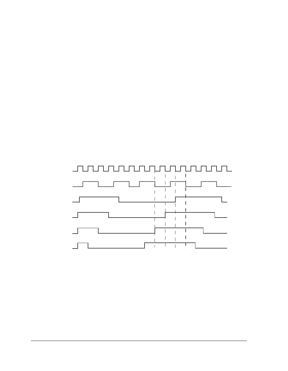
Figure 14-2. Phase and Pulse Width Settings
ENABLE
CLOCK INPUT
(BOTH CLK AND FS)
CLOCK OUTPUT
FS OUTPUT
(PHASE SHIFT =
PERIOD
-
1)
FS OUTPUT
(PHASE SHIFT = 0)
FS OUTPUT
(PHASE SHIFT = 1)
FS OUTPUT
(PHASE SHIFT = 2)
OTHER VALUES:
CLK DIVISOR = 4
FS DIVISOR = 16
PW = 8

 Loading...

