Pin Multiplexing
23-30 ADSP-214xx SHARC Processor Hardware Reference
• FLAGs (I/O)
• PWM channels (output)
Multiplexed External Port Pins
The external port address and data pins are used to multiplex the external
port interface with other peripherals. Table 23-15 provides the pin
settings.
Table 23-15 shows the following options.
• FLAGS can be mapped to any of the AMI pins.
• PDAP data/control can be completely moved to AMI pins (instead
of DAI pins).
• PDAP, PWM signals can be mapped only to the upper bits of the
AMI address pins
• FLAGS/PWM can be mapped (in groups of four) to any of the
upper 31–16 AMI address pins.
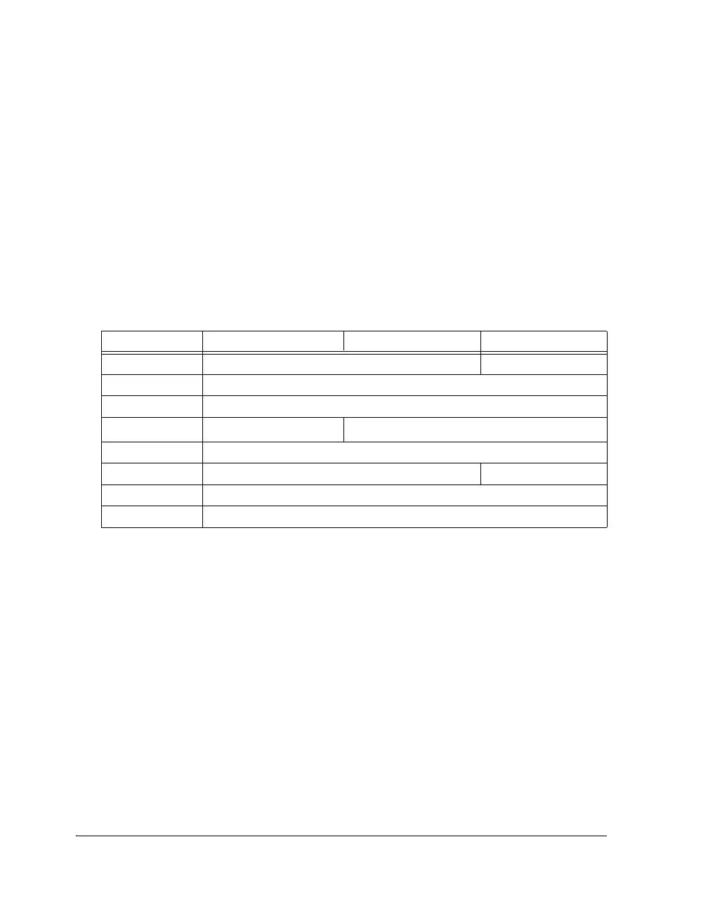
Table 23-15. EPDATA Truth Table (SYSCTL Register)
EPDATA ADDR31–16 ADDR15–8 DATA7–0
000 ADDR23–0 DATA7–0
001 Reserved
010 Reserved
011
FLAGS/PWM15–0
1
FLAGS15–0
100 Reserved
101 PDAP (DATA + CTRL) FLAGS7–0
110 Reserved
111 Three-state all pins

 Loading...

