ADSP-214xx SHARC Processor Hardware Reference A-217
Registers Reference
Shift Register Register
The following sections provide bit information for the shift register
register.
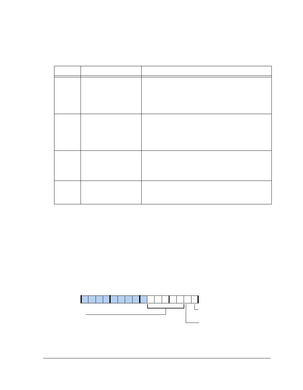
Control Register (SR_CTL)
This register, shown in Figure A-117 and described in Table A-117,
enables the peripheral.
Table A-116. RTC_INITSTAT Register Bit Descriptions (RO)
Bit Name Description
0ALRM_PEND
Time Calibration. Indicates that an alarm has occurred.
(Useful if core has powered down or reset in the middle).
0 = No daily alarm has occurred
1 = A daily alarm has occurred
This bit is cleared on reading RTC_INITSTAT.
1DAYALRM_PENDRTC Power Down. Indicates that an alarm has occurred.
(Useful if core has powered down or reset in the middle.)
0 = No day alarm has occurred
1 = A day alarm had occurred
This bit is cleared on reading RTC_INITSTAT.
2RTCPDN_STATPower Down Status. Status of RTC oscillator power-
down bit.
0 = The RTC oscillator is running
1 = The RTC oscillator is powered down
6–3 CALIB_STAT Calibration Status. Indicates whether CALIB value in the
RTC_INIT register has been successfully programmed in
the RTC. It should be equal to the value of CALIB.
Figure A-117. SR_CTL Register
SR_LDOE
SR_SDO_SEL (6–2)
Serial Data Out Select
Input
Parallel Data Output Enable
09 837564 2114 12 11 101315
SR_SW_CLR
Software Clear/Reset

 Loading...

