ADSP-214xx SHARC Processor Hardware Reference A-93
Registers Reference
IIR Debug Registers (IIRDEBUGCTL, IIRDEBUGADDR)
The
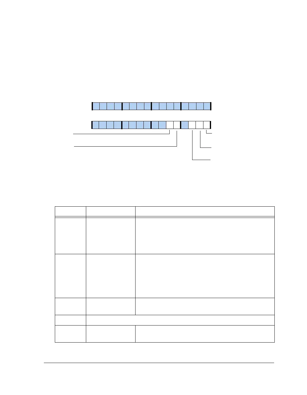
IIRDEBUGCTL register, shown in Figure A-44 and described in
Table A-56, controls the debug mode operation of the IIR accelerator.
Note that these registers should only be used in debug mode.
Figure A-44. IIRDEBUGCTL Register
Table A-56. IIRDEBUGCTL Register Bit Descriptions (RW)
Bits Name Description
0 IIR_DBGMODE Debug Mode Enable.
0 = Disable
1 = Enable
For local memory access, the IIRCTL1 register can be
cleared.
1IIR_HLDHold or Single Step. The function of this bit is based on the
IIR_DBGMEM bit setting.
For IIR_DBGMEM = 0:
1 = Single step
For IIR_DBGMEM = 1:
1 = Hold data
2IIR_RUNRelease the MAC. This bit is self clearing after one IIR clock
cycle.
3 Reserved
4 IIR_DBGMEM Local Memory Access. If set, the data and coefficients mem-
ory can be indirectly accessed.
IIR_DBGMODE
IIR_ADRINC
Address Auto Increment
Debug Mode Enable
31 302928 27 26 25 24 23 22 21 20 19 18 17 16
09 837564 2114 12 11 101315
IIR_HLD
Hold or Single Step
IIR_DBGMEM
Local Memory Access
IIR_RUN
Release MAC

 Loading...

