ADSP-214xx SHARC Processor Hardware Reference 22-9
Power Management
PLL Start-Up
Before the PLL can start settling, the RESET signal should be asserted for
several micro-seconds under the following conditions. For PLL informa-
tion, see the appropriate product data sheet.
• Valid and stable core voltage (
VDDINT)
• Valid and stable I/O voltage (
VDDEXT and VDD_DDR2)
• Valid and stable clock input (CLKIN)
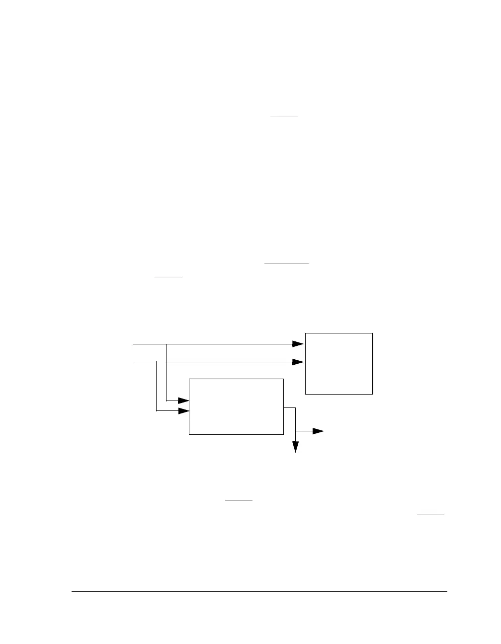
The chip reset circuit is shown in Figure 22-2. The PLL needs time to
lock to the CLKIN frequency before the core can execute or begin the boot
process. A delayed core reset signal (RESETOUT) is triggered by a 12-bit
counter after RESET is transitioned from low to high (approximately 400
μs for minimum CLKIN). The delay circuit is activated at the same time the
PLL is triggered for settling after reset is deasserted.
After the external processor RESET signal is deasserted, the PLL starts set-
tling. The rest of the chip is held in reset for 4096 CLKIN cycles after RESET
is deasserted by an internal reset signal.
Figure 22-2. Chip Reset Circuit
CLKIN
RESET
Delayed Internal
Core Processor Reset
PLL
Core Reset Delay Circuit
CLKIN
CORE_RST
CLKIN
PLL_RESET
12-bit Counter
Count 4096 CLKIN Cycles
ENA_CNT
RESETOUT

 Loading...

