Peripherals Routed Through the DPI
A-232 ADSP-214xx SHARC Processor Hardware Reference
Serial Peripheral Interface Registers
The following sections describe the registers associated with the two serial
peripheral interfaces (SPIs). Note that the SPI port is routed through the
DPI.
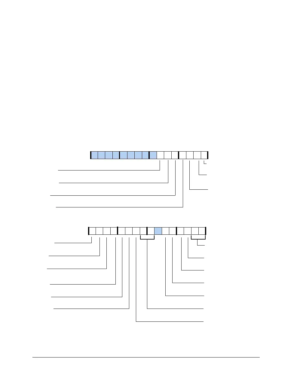
Control Registers (SPICTL, SPICTLB)
The SPI control (
SPICTL) registers are used to configure and enable the
SPI system. The bit settings for these registers are shown in Figure A-132
and described in Table A-122.
Figure A-132. SPICTL, SPICTLB Registers
PACKEN
TIMOD (0–1)
Transfer Initiation Mode
8-Bit Packing Enable
SPIEN
SPI System Enable
OPD
Open Drain Output Enable for
Data Pins
SPIMS
Master Slave Mode Bit
CLKPL
CPHASE
MSBF
Most Significant Byte First
SENDZ
Send Zero or Last Byte
GM
Fetch/Discard Incoming Data
ISSEN
Input Slave Select Enable
DMISO
Disable MISO Pin (Broadcast)
WL (8–7)
Word Length
Clock Polarity
Clock Phase
SGN
Sign Extend Data
SMLS
Seamless Transfer
TXFLSH
Transmit Buffer Flush
RXFLSH
Receive Buffer Flush
ILPBK
Internal Loopback Enable
AUTOSDS
Auto Slave Device Select
WTWDEN
Word to Word Delay Enable
31 302928 27 26 25 24 23 22 21 20 19 18 17 16
09 837564 2114 12 11 101315

 Loading...

