Effect Latency
16-20 ADSP-214xx SHARC Processor Hardware Reference
Write Effect Latency
For details on write effect latency, see the SHARC Processor Programming
Reference.
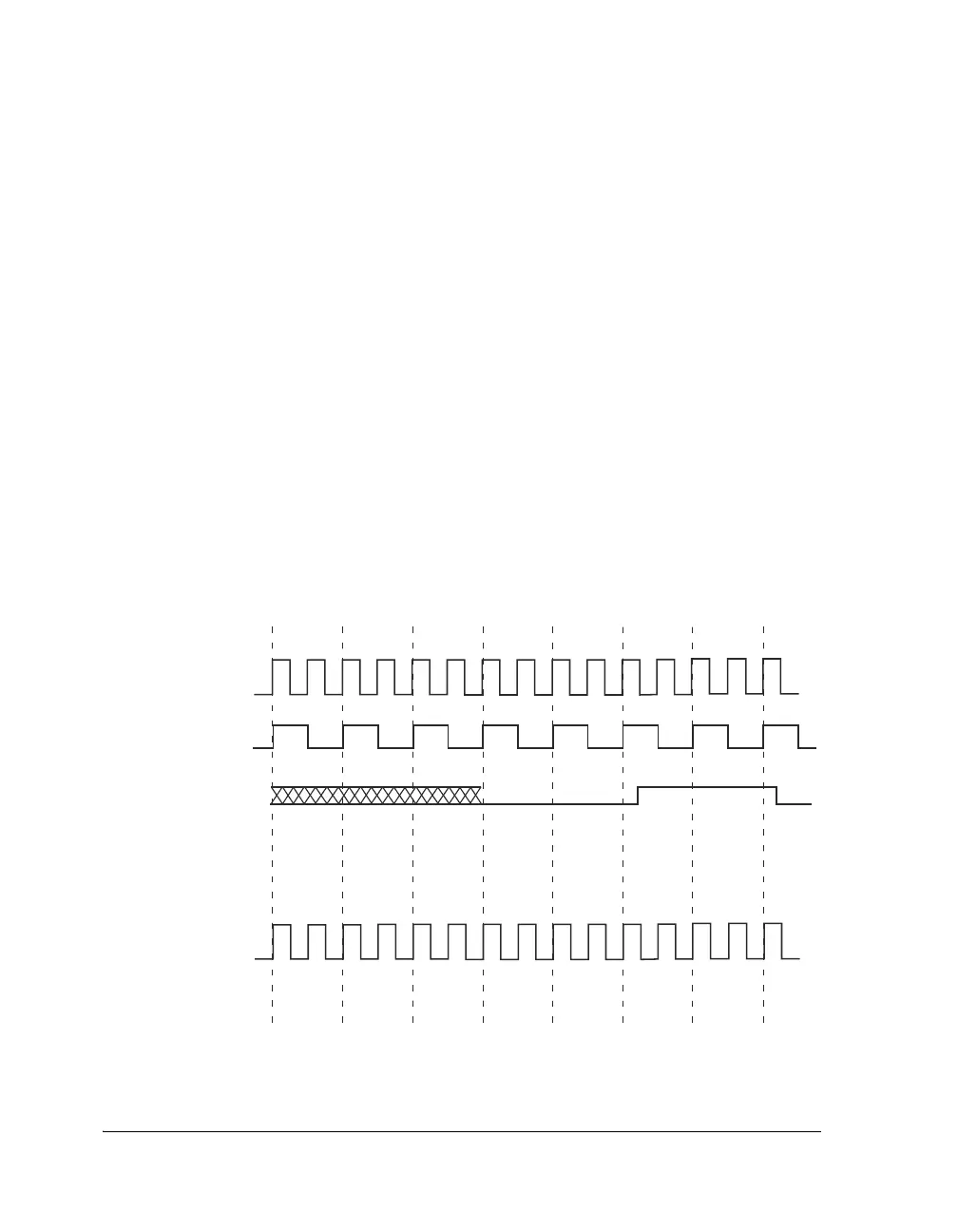
Peripheral Timers Effect Latency
After the timer registers are configured the effect latency is 3 PCLK cycles
enable and 2 PCLK cycles disable. The timer starts 3 PCLK cycles after the
TIMEN bit is set.
When the timer is enabled, the count register is loaded according to the
operation mode specified in the TMxCTL register. When the timer is dis-
abled, the counter registers retain their state; when the timer is re-enabled,
the counter is reinitialized based on the operating mode (Figure 16-9).
The program should never write the counter value directly.
Figure 16-9. Timer PWM Enable and Disable Timing
CCLK
PWMOUT
CCLK
TCOUNT
=M
TCOUNT
=M+1
TCOUNT
=M+1
TCOUNT
=M+1
TIMER ENABLE
SET
TIMEN
TIMER
ENABLED
TMxPRD = 0X2
TMxW = 0X1
TCOUNT
=XX
TCOUNT
=XX
TCOUNT
=1
TCOUNT
=2
TCOUNT
=4
TCOUNT
=3
TIMER
DISABLED
TIMER DISABLE
SET
TIMDIS
PCLK
TCOUNT
=XX
TCOUNT
=M+1

 Loading...

