ADSP-214xx SHARC Processor Hardware Reference 3-39
External Port
• 8 x 4-bit/page 2k words
The SDRAM’s page size is used to determine the system you select. All
four systems have the same external bank size, but different page sizes.
Note that larger page sizes, allow higher performance but larger page sizes
require more complex hardware layouts.
Even if connecting SDRAMs in parallel, the SDC always considers
the cluster as one external SDRAM bank because all address and
control lines feed the parallel parts as shown in Figure 3-10.
Buffering Controller for Multiple SDRAMs
If using multiples SDRAMs or modules, the capacitive load will exceed
the controller’s output drive strength. In order to bypass this problem an
external latch can be used for decoupling by setting the SDBUF (bit 23).
This adds a cycle of data buffering to read and write accesses. An example
single processor system is shown in Figure 3-10.
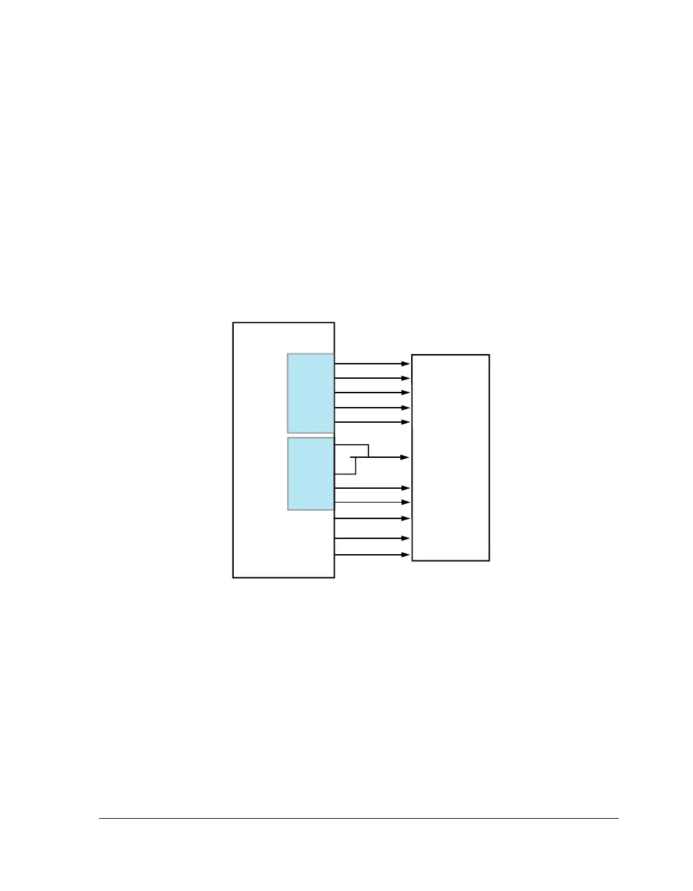
Figure 3-9. Single Processor System With SDRAM
DATA[15
-
0]
ADSP-2147x
MS3
RAS
CAS
SDWE
SDCKE
C
O
N
T
R
O
L
RAS
CAS
DQM
WE
CLK
CKE
SDRAM
8M x 16x 4
CS
BA1
BA0
A
D
D
R
E
S
S
SDCLK
A[15
-
0]
SDA10
A17
A18
A[9
-
0]
A[14
-
0]
DATA[15
-
0]
SDDQM

 Loading...

