Peripherals Routed Through the DPI
A-270 ADSP-214xx SHARC Processor Hardware Reference
Timer Configuration Registers (TMxCTL)
All timer clocks are gated off when the specific timer’s configuration regis-
ter is set to zero at system reset or subsequently reset by user programs.
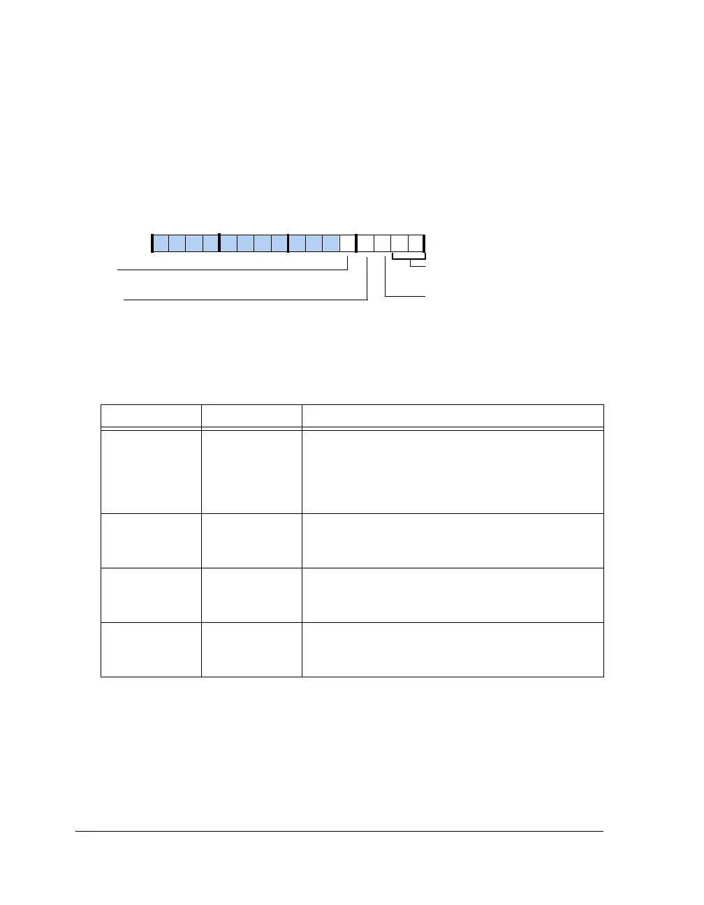
These registers are shown in Figure A-155.
Figure A-155. TMxCTL Register
Table A-146. TMxCTL Register Bit Descriptions (RW)
Bit Name Description
1–0 TIMODE Timer Mode.
00 = Reset
01 = PWM_OUT mode (TIMODEPWM)
10 = WDTH_CAP mode (TIMODEW)
11 = EXT_CLK mode (TIMODEEXT)
2PULSEPulse Edge Select.
1 = Positive active pulse
0 = Negative active pulse
3PRDCNTPeriod Count.
1 = Count to end of period
0 = Count to end of width
4IRQENInterrupt Enable.
1 = Enable
0 = Disable
TIMODE (1–0)
Interrupt Enable
PRDCNT
Pulse Edge Select
Timer Mode
PULSE
Period Count
IRQEN
09 837564 2114 12 11 101315

 Loading...

