ADSP-214xx SHARC Processor Hardware Reference A-243
Registers Reference
UART Control and Status Registers
The processor provides a set of PC-style, industry-standard control and
status registers for each UART. These IOP registers are byte-wide registers
that are mapped as half-words with the most significant byte zero-filled.
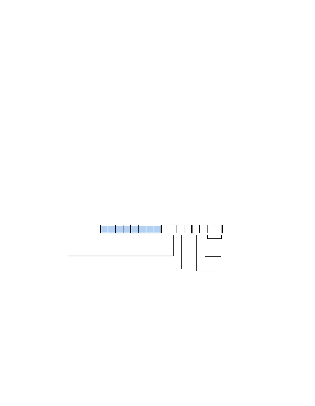
Line Control Register (UART0LCR)
The UART line control register (
UART0LCR, shown in Figure A-136 and
described in Table A-127) controls the format of received and transmitted
character frames.
Some UART registers share the same IOP address. The UART0DLL
registers are mapped to the same address as the UARTxTHR and
UART0RBR registers. The UART0DLH registers are mapped to the same
address as the interrupt enable registers (UART0IER). Note that the
UARTDLAB bit in the UART0LCR register must be set before the UART
divisor latch registers can be accessed. If the UARTDLAB bit is cleared,
access to the UART0THR and UART0RBR or UART0IER registers occurs.
Figure A-136. UART0LCR Register
UARTWLS (1–0)
Word Length Select
UARTSTB
Stop Bits
UARTSB
Stick Parity
UARTSTP
UARTPEN
Parity Enable
UARTEPS
Set Break
UARTDLAB
Divisor Latch Access
Even Parity Select
09 837564 2114 12 11 101315

 Loading...

