Peripherals Routed Through the DPI
A-242 ADSP-214xx SHARC Processor Hardware Reference
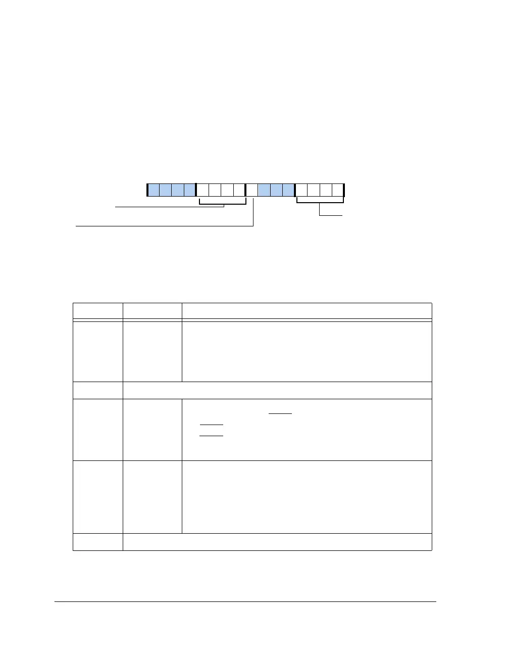
SPI Port Flags Registers (SPIFLG, SPIFLGB)
The
SPIFLG and SPIFLGB registers are used to enable individual SPI
slave-select lines when the SPI is enabled as a master. This register is
ignored if the SPI is programmed as s slave. The bit settings for these reg-
isters are shown in Figure A-135 and described in Table A-126.
Figure A-135. SPIFLG, SPIFLGB Registers
Table A-126. SPIFLG, SPIFLGB Register Bit Descriptions (RW)
Bit Name Description
3–0 DSxEN SPI Device Select Enable. Enables or disables the corresponding
output signal to the SRU2 be used for SPI slave-select.
0 = Disable SPIFLGx output enable
1 = Enable SPIFLGx output enable
Note DS0EN bit is set in SPI master mode only.
6–4 Reserved
7 (RO) ISSS Input Slave Service Select. Reflects the service selection for the
slave-select input pin (SPIDS).
0 =
SPIDS pin ignored
1 =
SPIDS pin used as multimaster error detection (default for SPI
only)
11–8 SPIFLGx SPI Device Select Control. Selects (if cleared, = 0) a correspond-
ing DPI pin (depending on pin routing) output to be asserted for
an SPI slave-select. For AUTOSDS=1, there is automatic HW
control regardless of CPHASE setting
0000 = All SPIFLGx cleared
1111 = All SPIFLGx set (default)
12–31 Reserved
SPIFLGx (11–8 )
DSxEN (3–0)
SPI Device Select Enable
SPI Device Select Control
ISSS
Status of input Slave-select Pin
09 837564 2114 12 11 101315

 Loading...

