ADSP-214xx SHARC Processor Hardware Reference A-249
Registers Reference
Divisor Latch Registers (UART0DLL, UART0DLH)
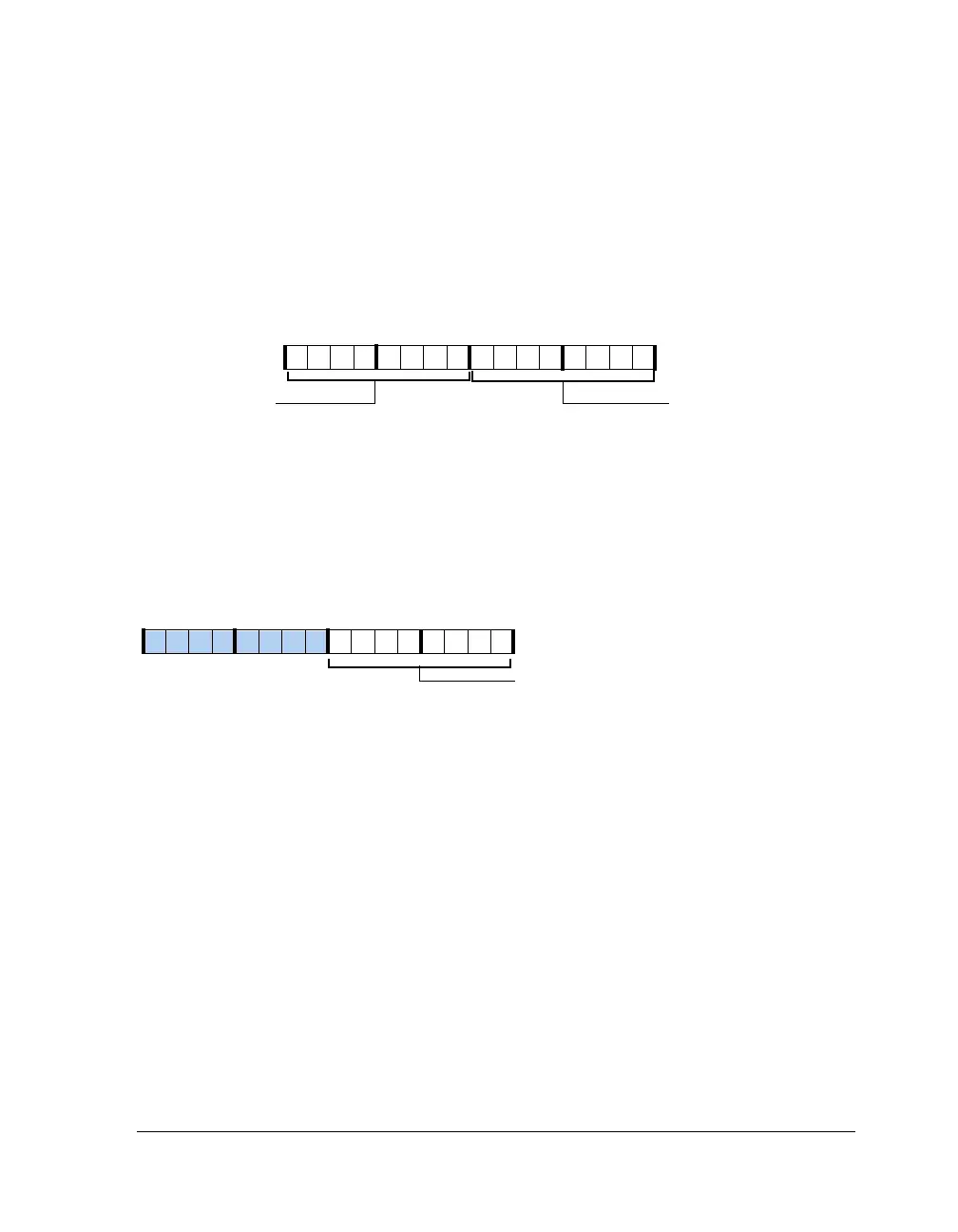
The bit rate is characterized by the peripheral clock (
PCLK) and the 16-bit
divisor. The divisor is split into the UART divisor latch low byte register
(UART0DLL) and the UART divisor latch high byte register (UART0DLH),
both shown in Figure A-140.
Scratch Register (UART0SCR)
This register (Figure A-141) is used for general-purpose data storage and
does not control the UART hardware in any way.
Mode Register (UART0MODE)
The UART mode register controls miscellaneous settings as shown in
Figure A-142 and described Table A-131.
Figure A-140. UART Divisor Latch Registers
Figure A-141. UART Scratch Registers
Divisor Latch
Low Byte (7–0)
Divisor Latch High
Byte (15–8)
09 837564 2114 12 11 101315
Scratch (7–0)
09 837564 2114 12 11 101315

 Loading...

