Peripherals Routed Through the DPI
A-250 ADSP-214xx SHARC Processor Hardware Reference
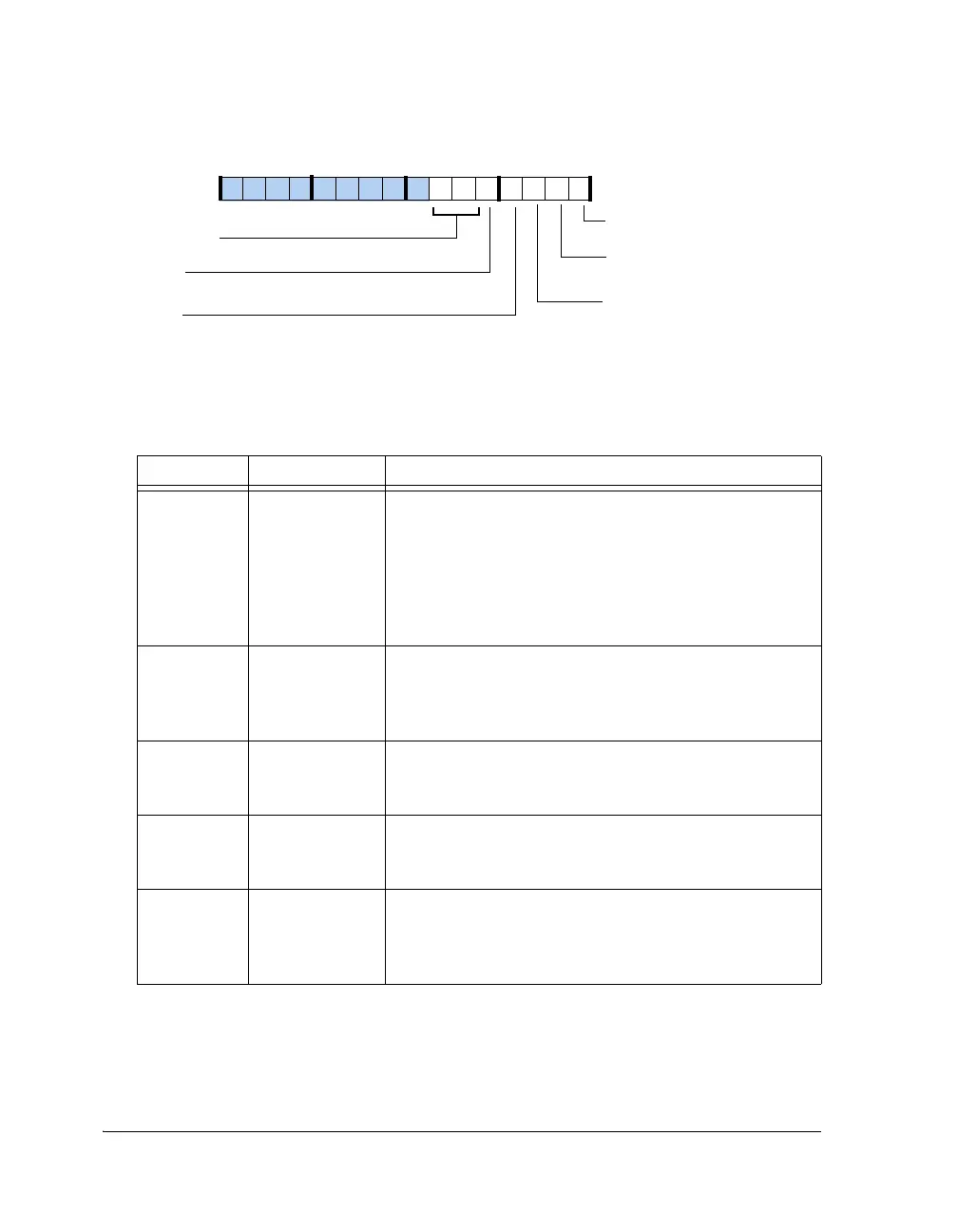
Figure A-142. UART Mode Register
Table A-131. UART Mode Register Bit Descriptions (RW)
Bit Name Description
0UARTPACKPacking Enable.
0 = No pack
1 = Packing enabled. Consecutive data words (example 0xAB
and 0xCD) are packed as 0x00CD 00AB in the receiver, and
0x00CD 00AB is transmitted as two words of 0xAB and
0xCD successively from the transmitter. For more informa-
tion, see “Data Packing” on page 20-8.
1 (WO) UARTPKSYN Synchronize Data Packing in RX. When written with a 1,
the next data byte goes to the lower byte position of the RBR
register. This is a write-only bit and always returns zero on
reads.
2 UARTTX9 Enable 9-Bit Tx in Transmitter.
0 = I/O mode
1 = 9-bit transmission in transmitter
3 UARTRX9 Enable 9-Bit Tx in Receiver.
0 = I/O mode
1 = 9-bit transmission in receiver
4UARTAENEnable Address Detect (If RX9 = 1).
0 = Disable address detection; all bytes are received
1 = Enable address detection; interrupt and load of RBR
when RX9D is set
UARTPACK
UARTPKSYN
Packing Enable
Synchronize Data Packing in Rx
UARTRX9
Enable 9-Bit Tx in Receive
UARTAEN
Enable Address Detect
UARTPST (6–5)
Pin Status
UARTTX9
Enable 9-Bit Tx in Transmitter
09 837564 2114 12 11 101315

 Loading...

