Operation Modes
10-24 ADSP-214xx SHARC Processor Hardware Reference
control (
SPCTLx) registers that must be set in order to configure each spe-
cific SPORT operation mode. The shaded columns indicate that the bits
come from different control registers.
The following sections provide detailed information on each operating
mode available using the serial ports. It should be noted that many bits in
the SPORT registers that control the function of the mode are the same
bit but have a different name depending on the operating mode. Further,
some bits are used in some modes but not others. For reference, see
Table 10-6 on page 10-22, Table 10-7, and “Serial Port Registers” on
page A-150.
Channel Order First
For left-justfied, I
2
S and packed modes the next table demonstrates which
word is transmitted or receive first depending on the
L_FIRST bit.
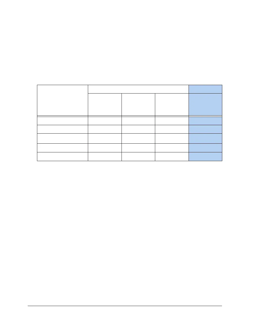
Table 10-7. SPORT Operation Modes
OPERATING MODES
(x = A or B or A and B
SPORT Channels)
SPCTLx Bits SPMCTLx Bits
OPMODE
(Bit 11)
OPMODE
(Bit 17)
SPEN_x
(Bit 0/24)
MCEx
Standard Serial Mode 0 Valid 1
0
Left-justified Mode 1 1 1
0
I
2
S Mode
101
0
Packed Mode 1 0 0
1
Multichannel Mode 0 0 0
1
 Loading...


