ADSP-214xx SHARC Processor Hardware Reference A-23
Registers Reference
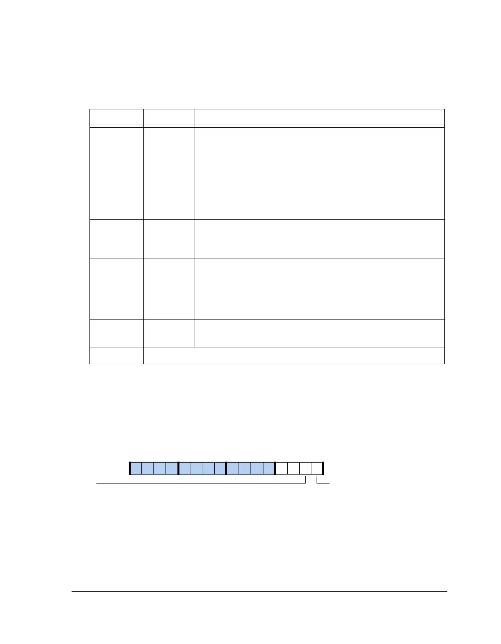
AMI Status Register (AMISTAT)
This 32-bit, read-only register provides status information for the AMI
interface and can be read at any time. This register is shown in Figure A-8
and described in Table A-10.
16–14 IC Bus Idle Cycle. Idle cycle to be inserted whenever read from exter-
nal memory is followed by a write to external memory – to avoid
contention. 'IC' EP clock cycles are ensured between a read to
write.
000 = 0 cycles, 001 = 1 cycle
010 = 2 cycles, 011 = 3 cycles
100 = 4 cycles, 101 = 5 cycles
110 = 6 cycles, 111 = 7 cycles
17 FLSH AMI Buffer Flush (Write-Only).
0 = Buffer holds the data
1 = Flush the buffer
20–18 RHC Read Hold Cycle at the End of Read Access. Controls the delay
between two reads.
000 = Disable read hold cycle
001 = Hold address for one cycle
010 = Hold address for two cycles
21 PREDIS Disable Predictive Reads. Default is predictive reads are enabled.
For more information, see “Read Optimazition” on page 3-43.
31–22 Reserved
Figure A-8. AMISTAT Register
Table A-9. AMICTLx Register Bit Descriptions (RW) (Cont’d)
Bit Name Description
AMIS
External Interface Status
09 837564 2114 12 11 101315
AMIMS
External Bus Master

 Loading...

