Operating Modes
15-16 ADSP-214xx SHARC Processor Hardware Reference
asserted (active-low) between transfers or be deasserted between transfers.
This is controlled in software using the
SPIFLGx bits (SPIFLG register). For
example, to configure SPI_FLG1_O as a slave-select, set DS1EN = 1 and
SPIFLG1 = 1. As soon as this SPIFLG register write takes effect, the
SPI_FLG1_O (slave-select output pin) becomes active (Low).
If needed, SPI_FLGx_O can be cycled high and low between transfers by
setting the
SPIFLG[x] bit to 1 and back to 0. Otherwise, SPI_FLGx_O
remains active between transfers.
If
CPHASE = 0 or CHPASE = 1 and AUTOSDS = 1, all selected outputs are
asserted only for the duration of the transfer. This is controlled by the
internal SPI hardware. In this case, the
SPIFLGx bits are ignored. For
example, to configure
SPI_FLG1_O as a slave-select, it is only necessary to
set
DS1EN=1.
Note that the SPI_FLGx_O signals behave as slave-select outputs only if the
SPI module is enabled as a master. Otherwise, none of the bits in the
SPIFLG register have any effect.
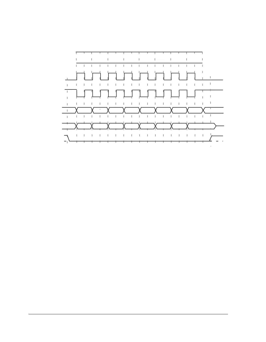
Figure 15-6. SPI Transfer Protocol for CPHASE = 1
1 2 3 4 5 6 7 8
*
6
6 5 4 3
5 4 3 2 1 LSB *
2 1 LSB
MSB
MSB
* = UNDEFINED
*
CLOCK CYCLE#
SPI_CLK_O
CLKPL=0
(SPI MODE 1)
SPI_CLK_O
CLKPL=1
(SPI MODE 3)
SPI_MOSI_O
FROM MASTER
SPI_MISO_O
FROM SLAVE
SPI_DS_I
TO MASTER

 Loading...

