ADSP-214xx SHARC Processor Hardware Reference 11-17
Input Data Port
Note that each input channel has its own clock and frame sync input, so
unused IDP channels do not produce data and therefore have no impact
on FIFO throughput. The clock and frame sync of any unused input
should be routed by the SRU to low to avoid unintentional acquisition.
The framing format is selected by using the
IDP_SMODEx bits (three bits per
channel) in the IDP_CTL0 register. Bits 31–8 of the IDP_CTL0 register con-
trol the input format modes for each of the eight channels. The eight
groups of three bits indicate the mode of the serial input for each of the
eight IDP channels.
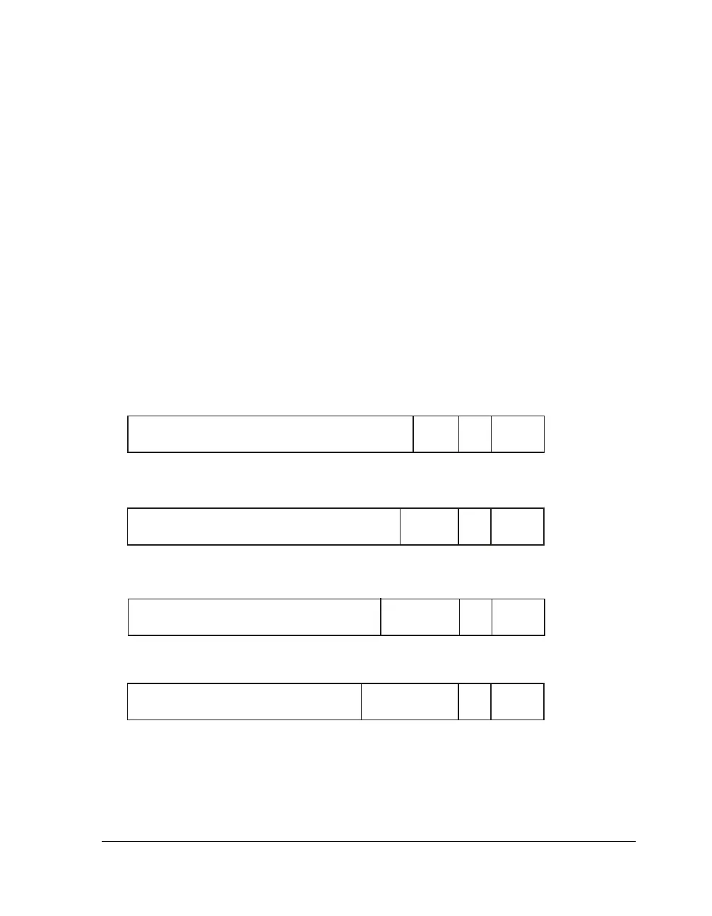
Figure 11-8 and Figure 11-7 shows the IDP data buffer input format for
the SIP (depending on SMODEx bits) for core access.
Figure 11-7. IDP Data Buffer Format SIP – Right-Justified
RIGHT-JUSTIFIED FORMAT, 24-BIT DATA WIDTH
24 BITS AUDIO DATA
4BITS,
SET TO
ZERO
L/R
BIT
3BITS
IDP
CHANNEL
RIGHT-JUSTIFIED FORMAT, 20-BIT DATA WIDTH
20 BITS AUDIO DATA
8BITS,
SET TO
ZERO
L/R
BIT
3BITS
IDP
CHANNEL
RIGHT-JUSTIFIED FORMAT, 18-BIT DATA WIDTH
18 BITS AUDIO DATA
10 BITS,
SET TO
ZERO
L/R
BIT
3BITS
IDP
CHANNEL
RIGHT-JUSTIFIED FORMAT, 16-BIT DATA WIDTH
16 BITS AUDIO DATA
12 BITS,
SET TO
ZERO
L/R
BIT
3BITS
IDP
CHANNEL

 Loading...

