Operating Modes
16-16 ADSP-214xx SHARC Processor Hardware Reference
After the timer is enabled, it waits for the first rising edge on the
TIMERx_I
signal. The rising edge forces the count register to be loaded by the value
(0xFFFF FFFF – TMxPRD). Every subsequent rising edge increments the
count register. After reaching the count value 0xFFFF FFFE, the TIMxIRQ
bit is set and an interrupt is generated. The next rising edge reloads the
count register with (0xFFFF FFFF – TMxPRD) again.
The EXT_CLK timing is shown in Figure 16-8.
The configuration bit,
PRDCNT, has no effect in this mode. Also, TIMxOVF is
never set and the width register is unused.
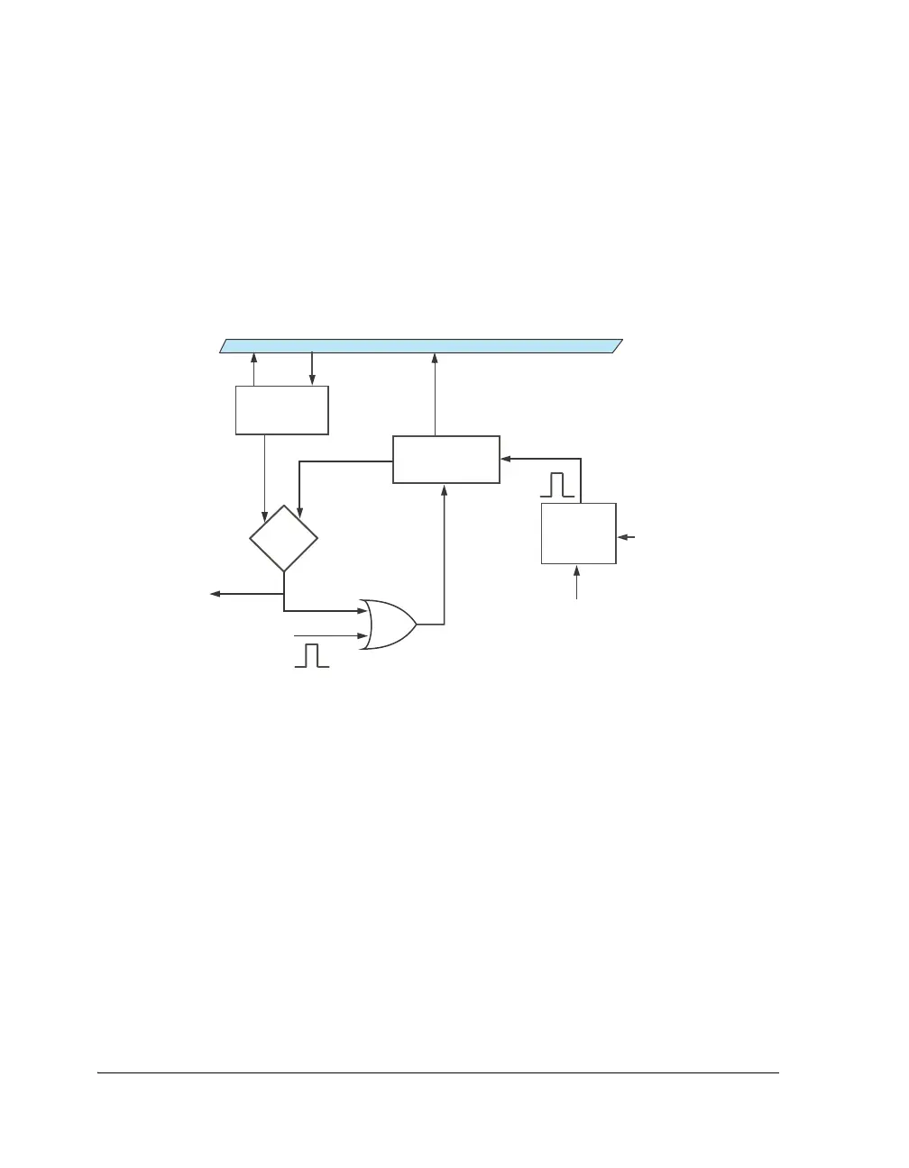
Figure 16-7. Flow Diagram EXT_CLK Mode
CLOCK
LEADING
EDGE
DETECT
TIMERx_COUNTER
TIMERx_PERIOD
TIMER_ENABLE
INTERRUPT
EQUAL?
Y
RESET
TIMERx_I
CORE BUS
PULSE

 Loading...
