ADSP-214xx SHARC Processor Hardware Reference 7-3
Pulse Width Modulation
• The emergency dead time insertion is implemented after the ‘ideal’
PWM output pair, including crossover, is generated.
• The output control unit allows the redirection of the outputs of the
two-phase timing unit for each channel to either the high-side or
the low-side output. In addition, the output control unit allows
individual enabling/disabling of each of the four PWM output
signals.
• The PWM interrupt controller generates an interrupt at the start of
the PWM period which is shared for all modules.
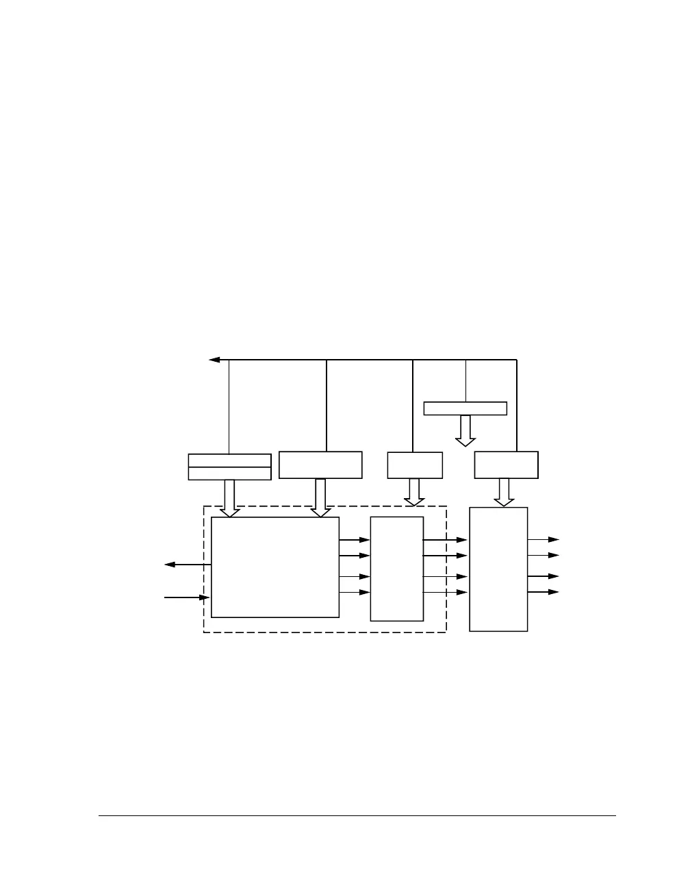
Figure 7-1. PWM Module Block Diagram
PWM CONTROL
PWM DUTY
CYCLE CONTROL
AH
AL
BH
BL
DEAD
TIME
CONTROL
UNIT
TWO-PHASE PWM
GENERATOR UNIT
OUTPUT
CONTROL
UNIT
PWM PERIOD
PWM
DEAD TIME
PWM STATUS
PWM OUTPUT
CONTROL
PCLK
PWM
INTERRUPT
CORE BUS

 Loading...

