Processor Booting
23-22 ADSP-214xx SHARC Processor Hardware Reference
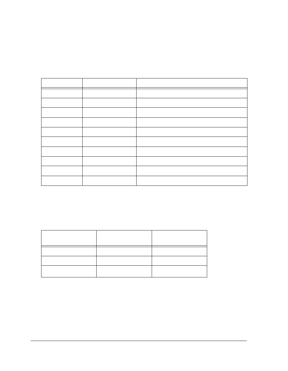
Table 23-11 shows the link port control settings after reset.
The DMA parameters for the Link Port0 channel are configured as shown
in Table 23-12.
Table 23-11. LPCTL0 Boot Settings (0x403)
Bit Name Setting
0 LEN Link port enabled (set = 1)
1 LDEN DMA enabled (set = 1)
2 LCHEN DMA Chaining (cleared = 0)
3 LTRAN Receive operation (cleared = 0)
7 BHD Buffer hang disabled (cleared = 0)
8 LTRQ_MSK LP transmit request mask (cleared = 0)
9 LRRQ_MSK LP receive request mask (cleared = 0)
10 DMACH_IRPT_MSK LP DMA channel interrupt unmask (P1I) (set = 1)
11 LPIT_MSK LP Invalid transmit mask (cleared = 0)
12 TXFR_DONE_MSK External transfer done interrupt mask (cleared = 0)
Table 23-12. Parameter Initialization for Link Boot
Parameter Register
Elf splitter
Initialization Value Comment
IILP0 IVT_START_ADDR Start of block 0
IMLP0 0x1 32-bit data transfers
ICLP0 0x180
384
× 32-bit transfers

 Loading...

