ADSP-214xx SHARC Processor Hardware Reference 16-9
Peripheral Timers
• Period value is lower than width value
• Width is equal to period
On invalid conditions, the timer sets both the TIMxOVF and the TIMIRQx
bits and the Count register is not altered. Note that after reset, the timer
registers are all zero. The PWM_OUT timing is shown in Figure 16-3.
As mentioned earlier, 2 x TMxPRD is the period of the PWM waveform and
2 x
TMxW is the width. If the period and width values are valid after the
timer is enabled, the count register is loaded with the value resulting from
0xFFFF FFFF – width. The timer counts upward to 0xFFFF FFFF.
Instead of incrementing to 0xFFFF FFFF, the timer then reloads the
counter with the value derived from 0xFFFF FFFF – (period – width) and
repeats.
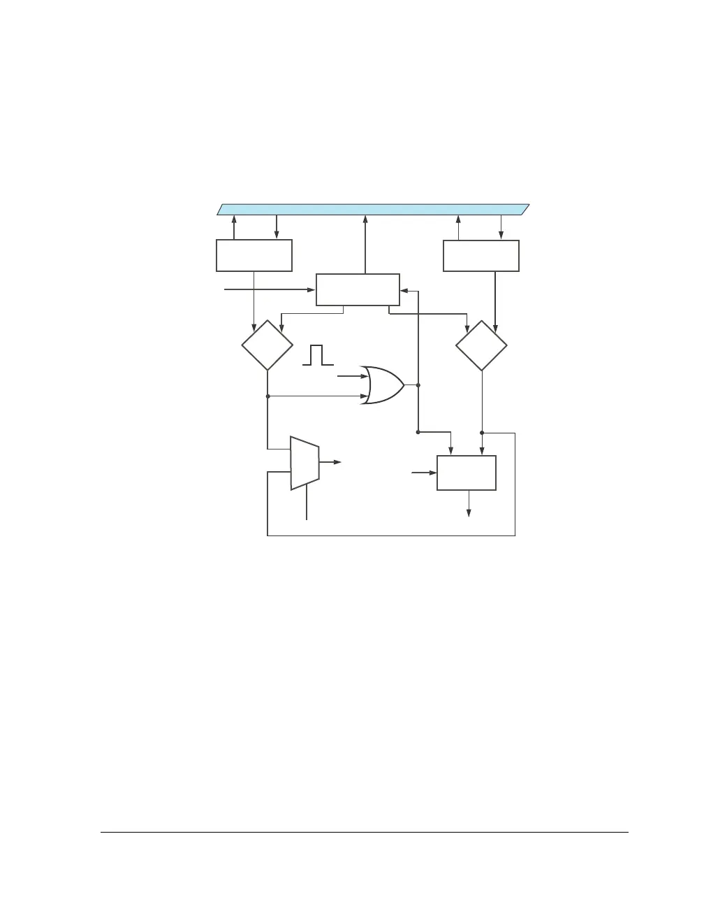
Figure 16-2. Timer Flow Diagram – PWM_OUT Mode
CORE BUS
PCLK
EQUAL?
TIMER_ENABLE
EQUAL?
1
0
YES
RESET
ASSERT DEASSERT
INTERRUPT
PERIOD_CNT
TIMERx_O
PWMOUT
LOGIC
PULSE
YES
TIMERx_COUNTER
TIMERx_PERIOD TIMERx_WIDTH
 Loading...


