Peripherals Routed Through the DPI
A-258 ADSP-214xx SHARC Processor Hardware Reference
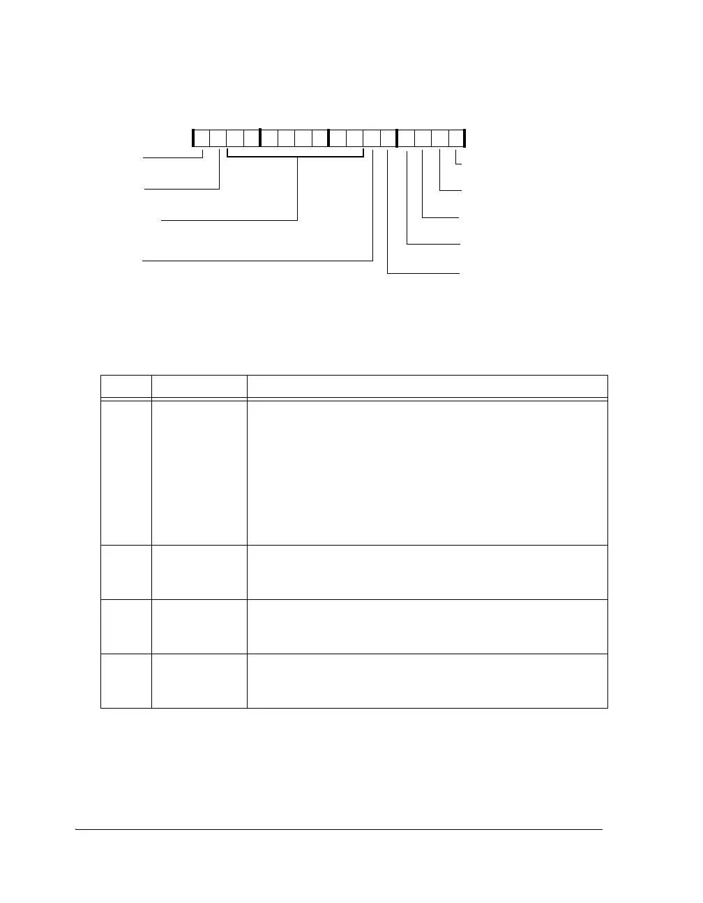
Figure A-148. TWIMCTL Register
Table A-140. TWIMCTL Register Bit Descriptions (RW)
Bit Name Description
0TWIMEN Master Mode Enable. Clears itself at the completion of a transfer.
This includes transfers terminated due to errors.
0 = Master mode functionality is disabled. If MEN is cleared during
operation, the transfer is aborted and all logic associated with master
mode transfers are reset. Serial data and serial clock (TWI_DATA,
TWI_CLOCK) are no longer driven. Write 1-to-clear status bits are
not effected.
1 = Master mode functionality is enabled. A START condition is gen-
erated if the bus is idle.
1TWIMLENMaster Address Length.
0 = Address is 7-bit
1 = Reserved. Setting this bit to one causes unpredictable behavior.
2TWIMDIR Master Transfer Direction.
0 = The initiated transfer is master transmit
1 = The initiated transfer is master receive
3TWIFAST Fast Mode.
0 = Standard mode timing specifications in use
1 = Fast mode timing specifications in use
TWIMEN
TWIMDIR
TWISDAOVR
TWISCLOVR
TWIDCNT (13–6)
TWIFAST
TWISTOP
TWIRSTART
TWIMLEN
Master Mode Enable
Master Address Length
Master Transfer Direction
Fast Mode
Issue Stop Condition
Serial Data Override
Number of Data Bytes to
Transfer
Repeat Start
Serial Clock Override
09 837564 2114 12 11 101315

 Loading...

