ADSP-214xx SHARC Processor Hardware Reference 10-17
Serial Ports
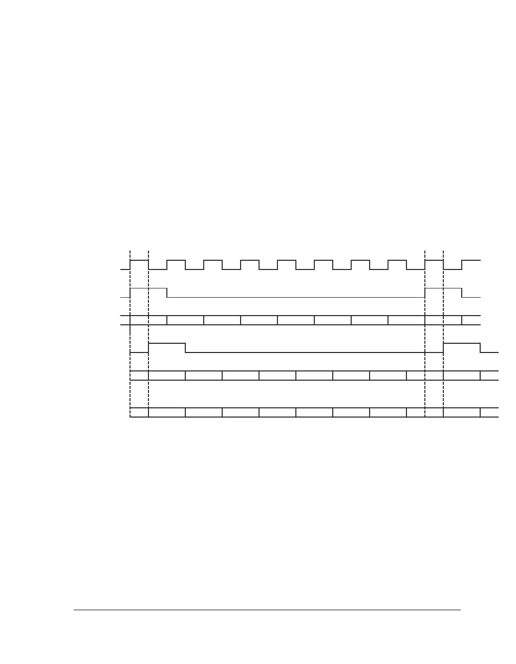
As shown in Figure 10-3 the SPORT uses two control signals to sample
data.
1. Serial clock (
SCLK) applies the bit clock for each serial data.
2. Frame sync (FS) divides the incoming data stream into frames.
Frames define the required data length (after the serial to parallel conver-
sion) necessary to store the data in memory for further processing as
shown in Figure 10-3. The transmitter for example drives clock and frame
sync called master while the receiver is slave sampling these data.
After the slave is sampled the
FS the SLEN word counter is reloaded to the
maximum setting. Each
SCLK decrements the SLEN counter until the full
frame is received. If the transmitter drives the frame sync and data on the
rising edge, the falling edge is used to sample the frame sync and data, and
vice versa.
Figure 10-3. Frame Sync and Data Driven on Rising Edge
DRIVE
SCLK
SDRIVE
DATA
DRIVE
FS
D7 D6 D5 D4 D3 D2 D1 D0
76543210
D7 D6 D5 D4 D3 D2 D1 D0
SAMPLED
FS
SAMPLED
DATA
SLEN
COUNTER

 Loading...
