Peripheral Registers
A-88 ADSP-214xx SHARC Processor Hardware Reference
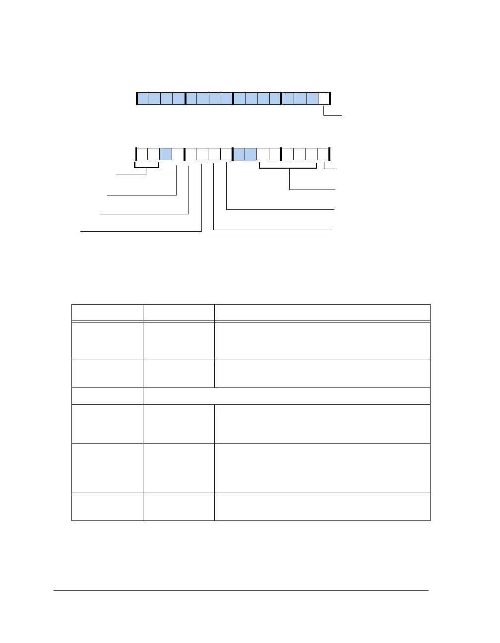
Figure A-40. IIRCTL1 Register
Table A-52. IIRCTL1 Register Bit Descriptions (RW)
Bits Name Description
0IIR_ENIIR Enable.
0 = IIR disabled
1 = IIR enabled
5–1 IIR_NCH Number of Channels. Programmable between 0–23
Channels = NCH + 1
7–6 Reserved
8 IIR_DMAEN DMA Enable.
0 = Disable
1 = Enable
9IIR_CAIChannel Auto Iterate.
0 = Processing stops once all channels are over
1 = Moves to first channel and continues processing in a
loop when all channels are over
10 IIR_SS Save State. Stores the Dk registers settings into local mem-
ory.
IIR_EN
NCH (5–1)
Number of Channels
Accelerator Enable
IIR_DMAEN
DMA Enable
IIR_FORTYBIT
40-Bit Floating-Point Select
31 302928 27 26 25 24 23 22 21 20 19 18 17 16
09 837564 2114 12 11 101315
IIR_RND (16–14)
Rounding Mode
IIR_RND (16–14)
Rounding Mode Select
For Floating-point Mode
IIR_CCINTR
Channel Complete Interrupt
IIR_CAI
Channel Auto Iterate
IIR_SS
Save State

 Loading...

