S/PDIF Transmitter
13-8 ADSP-214xx SHARC Processor Hardware Reference
off-board connections to other S/PDIF receivers. The output is also avail-
able to the S/PDIF receiver for loop-back testing through SRU.
In addition to encoding the audio data in the bi-phase format, the trans-
mitter also provides a way to easily add the channel status information to
the outgoing bi-phase stream. There are status/user registers for a frame
(192-bits/24 bytes) in the transmitter that correspond to each channel or
subframe. For more information, see “Transmitter Registers” on
page A-199.
Validity bits for both channels may also be controlled by the transmitter
control register. Optionally, the user bit, validity bit, and channel status
bit are sent to the transmitter with each left/right sample. For each sub-
frame the parity bit is automatically generated and inserted into the
bi-phase encoded data. A mute control and support for double-frequency
single-channel mode are also provided. The serial data input format may
be selected as left-justified, I
2
S, or right-justified with 16-, 18-, 20- or
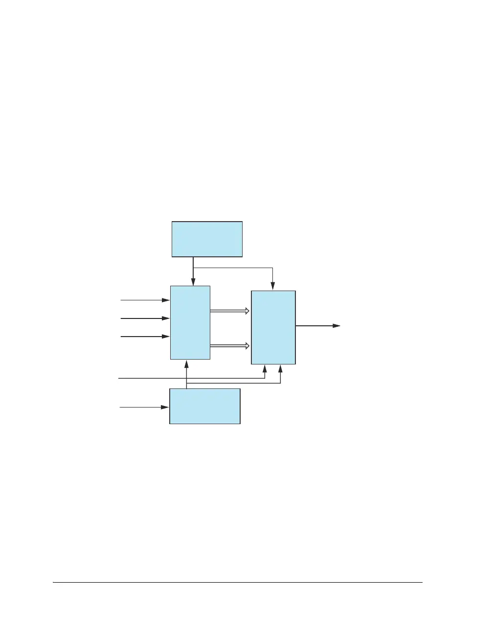
Figure 13-1. S/PDIF Transmitter Block Diagram
S/PDIF
SERIAL TO
PARALLEL
CONVERTER
AES3
TRANSMITTER
DIT_DATA_I
AUDIO
SAMPLES
DIT_CLK_I
DIT_O
(BIPHASE OUT)
CONTROL
TRANSMITTER
CONTROL REGISTER
BIPHASE
CLOCK
TX_BIPHASE_CLK
DIT_FS_I
DIT_EXTSYNC_I
DIT_HFCLK_I

 Loading...

