ADSP-2147x, ADSP-2148x External Port Registers
A-56 ADSP-214xx SHARC Processor Hardware Reference
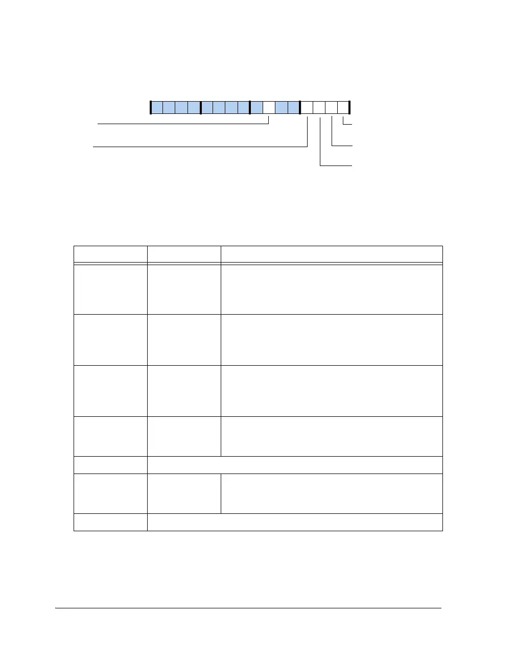
Figure A-24. SDSTAT0 Register
Table A-29. SDSTAT0 Register Bit Descriptions (RO)
Bit Name Description
0SDCISDC Idle. This bit is set if the SDC is performing a com-
mand or auto-refresh. If no access, this bit is cleared.
0 = SDC idle
1 = SDC access
1SDSRASDC Self-Refresh Mode. If set, controller is in self-refresh
mode .
0 = Non self-refresh mode (SDCKE pin high)
1 = Self-refresh mode (SDCKE pin low)
2SDPUASDC Power-Up Active. If set, controller is in power-up
mode.
0 = Non power-up mode (SDPSS-bit cleared in SDCTL)
1 = Power-up mode (SDPSS-bit set in SDCTL)
3SDRSSDC Reset State. If set, power-up sequence occurred.
0 = No power-up sequence
1 = Power-up sequence occurred
5–4 Reserved
6SDPENDSDC Controller Pipeline Status.
0 = No access pending in controller pipeline
1 = Read/Write access pending in controller pipeline.
15–7 Reserved
SDPUA
SDCI
SDRAM Controller Idle
SDSRA
SDRAM Self-Refresh Active
SDRAM Power-Up Active
SDRS
SDRAM In Reset State
SDPEND
SDRAM Pipeline Status
09 837564 2114 12 11 101315

 Loading...

