Peripherals Routed Through the DAI
A-180 ADSP-214xx SHARC Processor Hardware Reference
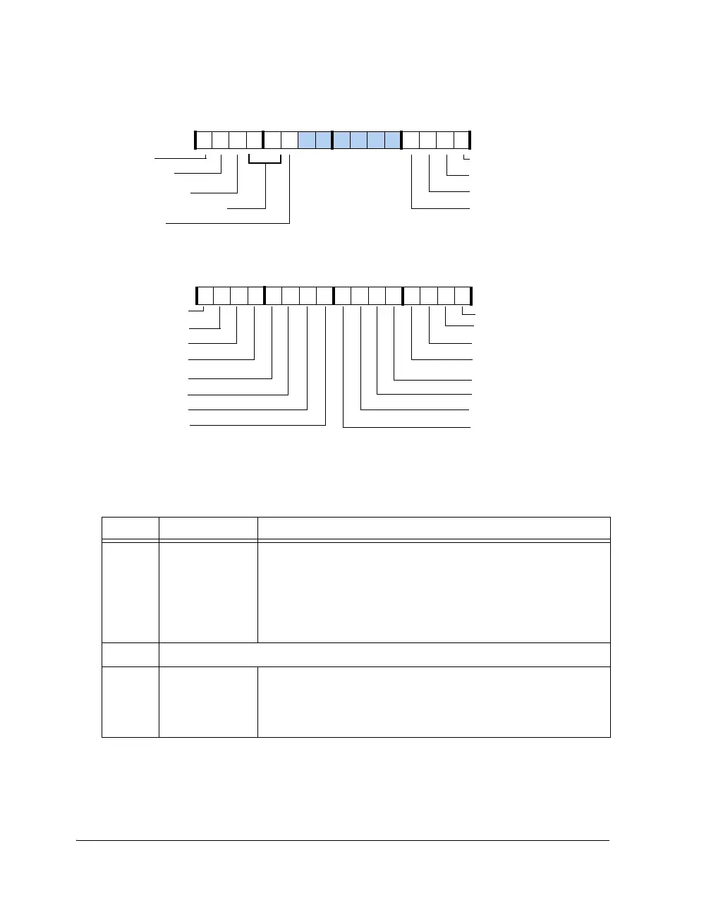
Figure A-96. IDP_PP_CTL Register
Table A-93. IDP_PP_CTL Register Bit Descriptions (RW)
Bit Name Description
19–0 IDP_P20–1_
PDAPMASK
Parallel Data Acquisition Port Mask. For each of the parallel
inputs:
0 = Input data from PDAP_20-1 are masked
1 = Input data from PDAP_20-1 are unmasked
After this masking process, data gets passed along to the packing
unit.
25–20 Reserved
26 IDP_PP_
SELECT
PDAP Port Select. This bit selects which peripheral is connected
to the PDAP unit.
0 = Data/control bits are read from DAI pins
1 = Data/control bits are read from AMI_ADDR pins
IDP_P12_PDAPMASK
IDP_P16_PDAPMASK
IDP_PDAP_EN
IDP_P19_PDAPMASK
IDP_P18_PDAPMASK
IDP_P17_PDAPMASK
IDP_P15_PDAPMASK
IDP_P14_PDAPMASK
IDP_P13_PDAPMASK
IDP_P01_PDAPMASK
IDP_P02_PDAPMASK
IDP_P03_PDAPMASK
IDP_P04_PDAPMASK
IDP_P05_PDAPMASK
IDP_P06_PDAPMASK
IDP_P11_PDAPMASK
IDP_P10_PDAPMASK
IDP_P09_PDAPMASK
IDP_P07_PDAPMASK
IDP_P08_PDAPMASK
IDP_PDAP_RESET
IDP_PDAP_CLKEDGE
IDP_PDAP_PACKING (28–27)
IDP_PP_SELECT
IDP_P20_PDAPMASK
31 302928 27 26 25 24 23 22 21 20 19 18 17 16
09 837564 2114 12 11 101315

 Loading...

