ADSP-214xx SHARC Processor Hardware Reference A-187
Registers Reference
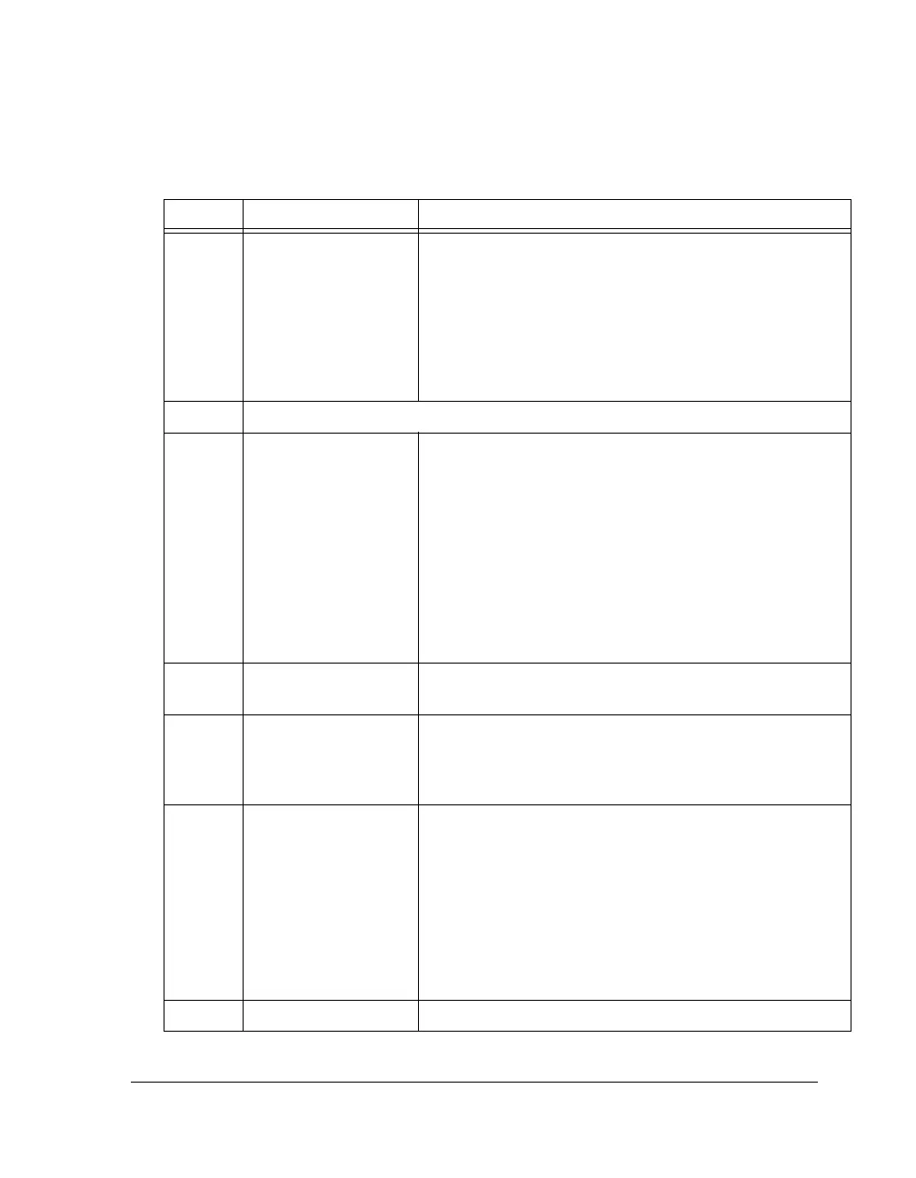
12–13 SRCx_LENOUT Output Word Length Select. Selects the serial output word
length on SRC 0, 2 as follows:
00 = 24 bits
01 = 20 bits
10 = 18 bits
11 = 16 bits
Any word length less than 24 bits has dither added to the
unused LSBs if SRCx_DITHER is enabled (= 1).
14 Reserved
15 SRCx_ENABLE SRC0 Enable. Enables SRC 0, 2. When (set = 1), or when the
sample rate (frame sync) between the input and output changes,
the SRC begins its initialization routine where; 1)
MUTE_OUT is asserted, 2) soft mute control counter for input
samples is set to maximum attenuation (–144 dB). Note that
SRC power-up completion is finished by clearing the
SRCx_MUTEOUT bit in SRCRATx register. Writes to the
SRCCTLx register should be at least one cycle before setting the
SRCx_ENABLE. When setting and clearing this bit, it should
be held low for a minimum of 5 PCLK cycles. Programs should
disable the SRC when changing modes.
16 SRCy_HARD_MUTE Hard Mute. Hard mutes SRC 1, 3.
1 = Mute (default)
17 SRCy_AUTO_MUTE Auto Hard Mute. Auto hard mutes SRC 1, 3 when
non audio is asserted by the SPDIF receiver.
0 = No mute
1 = Mute (default)
18–20 SRCy_SMODEIN Serial Input Format. Selects the serial input format for SRC 1,
3 as follows:
000 = Default, format is left-justified
001 = I
2
S
010 = TDM
100 = 24-bit right-justified
101 = 20-bit right-justified
110 = 18-bit right-justified
111 = 16-bit right-justified
21 SRCy_BYPASS Bypass Mode Enable. Output of SRC 1, 3 is the same as input.
Table A-96. SRCCTLx Register Bit Descriptions (RW) (Cont’d)
Bit Name Description

 Loading...

