Peripherals Routed Through the DAI
A-186 ADSP-214xx SHARC Processor Hardware Reference
2–4 SRCx_SMODEIN Serial Input Format. Selects the serial input format for SRC 0,
2 as follows:
000 = Default, format is left-justified
001 = I
2
S
010 = TDM
100 = 24-bit right-justified
101 = 20-bit right-justified
110 = 18-bit right-justified
111 = 16-bit right-justified
5SRCx_BYPASS Bypass SRCx. Output of SRC 0, 2 is the same as the input.
6–7 SRCx_DEEMPHASIS De-emphasis Filter Select. Used to de-emphasize audio data
that has been emphasized. The type of de-emphasis filter is
selected by the SRCx_DEEMPHASIS bits and is based on the
input sample rate (SRCx_FS_IP_I signal) as follows: enables
de-emphasis on incoming audio data for SRC 0, 2.
00 = No de-emphasis
01 = 32 kHz
10 = 44.1 kHz
11 = 48 kHz
8 SRCx_SOFTMUTE Soft Mute. Enables soft mute on SRC 0, 2.
0 = No mute
1 = Mute (default)
9SRCx_DITHERDither Select. Enables dithering on SRC 0, 2 when a word
length less than 24 bits is selected.
0 = Dithering is enabled (default)
1 = Dithering is disabled
10–11 SRCx_SMODEOUT Serial Output Format. Selects the serial output format on SRC
0, 2 as follows:
00 = Left-justified (default)
01 = I
2
S
10 = TDM mode
11 = Right-justified. The right-justified serial data out
mode assumes 64 SCLK cycles per frame, divided evenly for left
and right. For the other modes these 8 LSBs contain zeros.
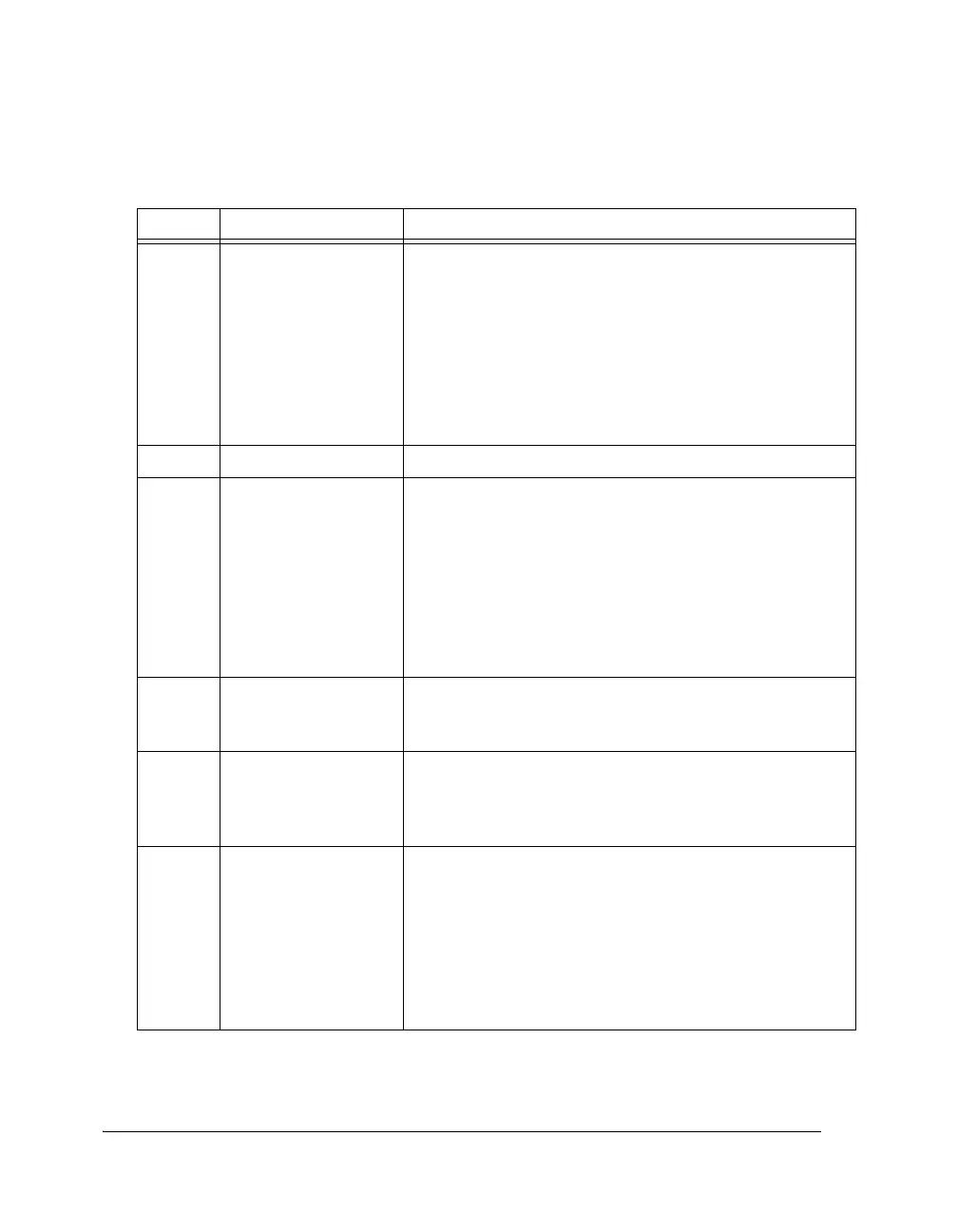
Table A-96. SRCCTLx Register Bit Descriptions (RW) (Cont’d)
Bit Name Description

 Loading...

