Peripherals Routed Through the DAI
A-200 ADSP-214xx SHARC Processor Hardware Reference
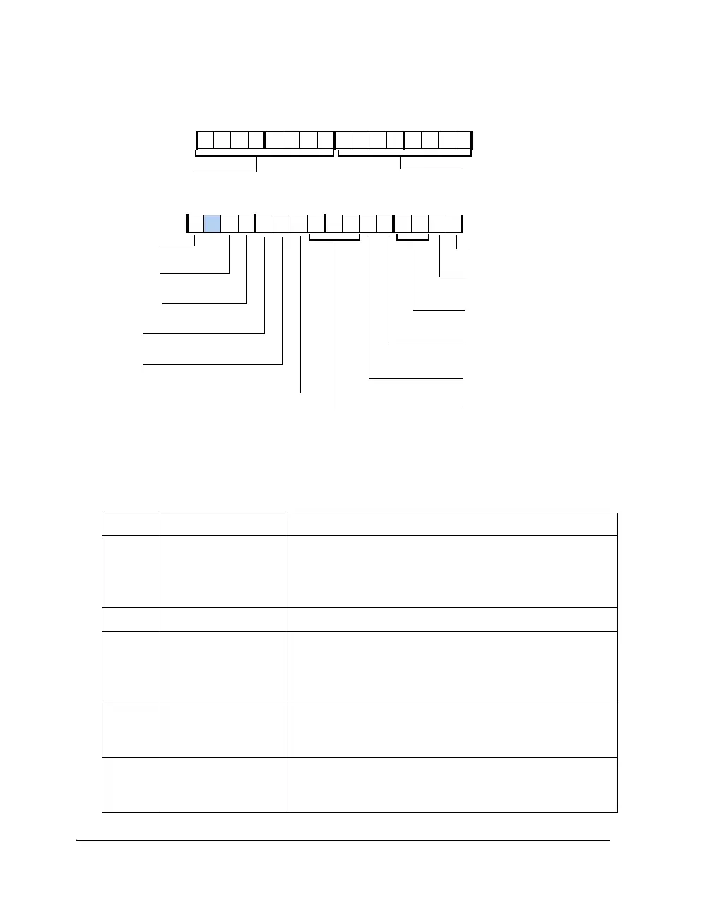
Figure A-107. DITCTL Register
Table A-104. DITCTL Register Bit Descriptions (RW)
Bit Name Description
0DIT_EN Transmitter Enable. Enables the transmitter and resets the
control registers to their defaults.
0 = Transmitter disabled
1 = Transmitter enabled
1DIT_MUTE Mute. Mutes the serial data output.
3–2 DIT_FREQ Frequency Multiplier. Sets the over sampling ratio to the fol-
lowing:
00 = 256 × frame sync
01 = 384 × frame sync
4DIT_SCDF Single-Channel, Double-Frequency Mode Enable.
0 = 2 channel mode
1 = SCDF mode
5DIT_SCDF_LRSelect Single-Channel, Double-Frequency Mode.
0 = Left channel
1 = Right channel
DIT_EN
DIT_MUTE
DIT_VALIDL
DIT_VALIDR
DIT_B0CHANR (31–24)
Channel Status Byte 0 for Subframe B
Validity Bit B
Validity Bit A
Mute Serial Data Output
Transmitter Enable
DIT_B0CHANL (23–16)
Channel Status Byte 0 for
Subframe A
DIT_AUTO
Automatically Block Start
DIT_SMODE_IN (8–6)
Serial Data Input Format
DIT_FREQ (3–2)
Oversampling ratio
DIT_SCDF
DIT_SCDF_LR
Select SCDF Channel
DIT_BLKSTART
Block Start
Single Channel Double Fre-
quency Mode Enable
DIT_USRPEND
Status Bit
EXT_SYNC_EN
External Sync Enable
31 302928 27 26 25 24 23 22 21 20 19 18 17 16
09 837564 2114 12 11 101315

 Loading...

