ADSP-214xx SHARC Processor Hardware Reference A-207
Registers Reference
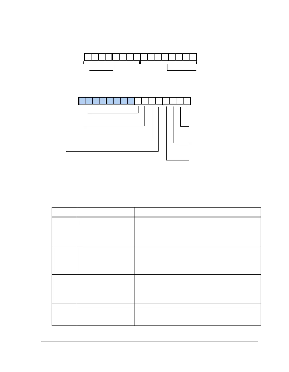
Figure A-109. DIRSTAT Register
Table A-110. DIRSTAT Register Bit Descriptions (RO)
Bit Name Description
0 DIR_NOAUDIOL Non-Audio Subframe Mode Channel 1. Based on SMPTE
337M.
0 = Not non-audio subframe mode
1 = Non-audio subframe mode, channel 1
1 DIR_NOAUDIOR Non-Audio Subframe Mode Channel 2. Based on SMPTE
337M.
0 = Not non-audio subframe mode
1 = Non-audio subframe mode, channel 2
2 DIR_NOAUDIOLR Non-Audio Frame Mode Channel 1 and 2. Based on
SMPTE 337M.
0 = Not non-audio frame mode
1 = Non-audio frame mode
3 (ROC) DIR_VALID Validity Bit. ORed bits of channel 1 and 2.
0 = Linear PCM data
1 = Non-linear audio data
DIR_NOAUDIOL
DIR_BIPHASEERROR
Biphase Error
Non-Audio Subframe Mode
Channel 1
DIR_B0CHANL (23–16)
DIR_VALID
Validity Bit. ORed value of chan-
nel 1 and 2
DIR_PARITYERROR
Parity bit. Indicates parity error
DIR_NOSTREAM
Stream Disconnected
DIR_LOCK
Lock Receiver
DIR_NOAUDIOR
Non-Audio Subframe Mode
Channel 2
DIR_NOAUDIOLR
Non-Audio Subframe Mode
Channel 1 and 2
DIR_B0CHANR (31–24)
Channel S tatus Byte 0 for
Subframe A
Channel Status Byte 0 for Subframe B
31 302928 27 26 25 24 23 22 21 20 19 18 17 16
09 837564 2114 12 11 101315

 Loading...

