ADSP-214xx SHARC Processor Hardware Reference 23-13
System Design
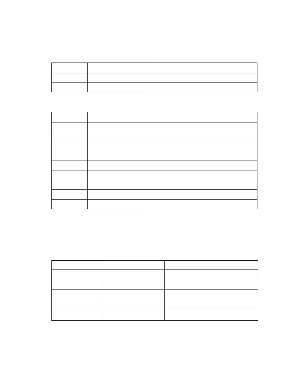
The SPI DMA channel is used when downloading the boot kernel infor-
mation to the processor. At reset, the DMA parameter registers are
initialized to the values listed in Table 23-8.
FIFOFLSH Cleared (= 0) FIFO flush
INTERR Cleared (= 0) SPI DMA error interrupts
Table 23-7. SPICTL Master Boot Settings (0x5D06)
Bit Setting Comment
SPIEN Set (= 1) SPI enabled
SPIMS Set (= 1) Master device
MSBF Cleared (= 0) LSB first
WL 10 32-bit SPI receive shift register word length
DMISO Cleared (= 0) MISO enabled
SENDZ Set (= 1) Send zeros
SPIRCV Set (= 1) Receive DMA enabled
CLKPL Set (= 1) Active low SPI clock
CPHASE Set (= 1) Toggle SPICLK at the beginning of the first bit
Table 23-8. Parameter Initialization Values for SPI Master Boot
Parameter Register Initialization Value Comment
SPIBAUD 0x64 SPICLK = PCLK/100
SPIFLG 0xFE01 SPI_FLG0_O used as slave-select
IISPI IVT_START_ADDR Start of block 0
IMSPI 0x1 32-bit data transfers
CSPI 0x180
384
× 32-bit transfers
Table 23-6. SPIDMAC Master/Slave Boot Settings (0x7) (Cont’d)
Bit Setting Comment

 Loading...

