System and Power Management Registers
A-10 ADSP-214xx SHARC Processor Hardware Reference
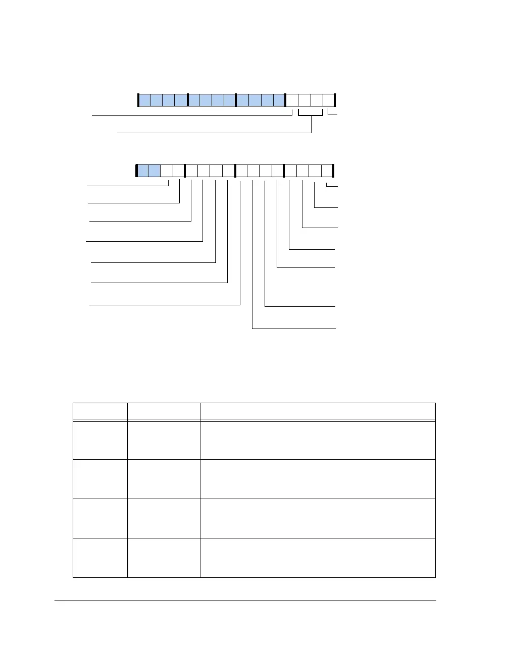
Figure A-3. PMCTL1 Register
Table A-4. PMCTL1 Register Bit Descriptions (RW)
Bit Name Description
0 UART0OFF Shutdown Clock to UART.
0 = UART is in normal mode
1 = Shutdown clock to UART
1TWIOFFShutdown Clock to TWI.
0 = TWI is in normal mode
1 = Shutdown clock to TWI
2PWMOFFShutdown Clock to PWM.
0 = PWM is in normal mode
1 = Shutdown clock to PWM
3DTCPOFFShutdown Clock to MTM/DTCP.
0 = MTM is in normal mode
1 = Shutdown clock to MTM
LP0OFF
ACCOFF
Accelerator Clocks
Shutdown
ACCSEL (18–17)
Accelerator Select
UART0POFF
UART Clock Shutdown
MLBOFF
MLB Clock Shutdown
LP0 Clock Shutdown
TWIOFF
TWI Clock Shutdown
PWMOFF
PWM Clock Shutdown
DTCPOFF
DTCP Clock Shutdown
DAIOFF
Shutdown Clock to SRC,
SPDIF, SRU, PCG, DAI, IDP,
PDAP
EPOFF
EP Clock Shutdown
SP01OFF
SP0/1 Clock Shutdown
SP23OFF
SP2/3 Clock Shutdown
SP67OFF
SP6/7 Clock Shutdown
SP45OFF
SP4/5 Clock Shutdown
TMROFF
Timer Clock S hutdown
SPIOFF
SPI Clock Shutdown
LP1OFF
LP1 Clock Shutdown
31 302928 27 26 25 24 23 22 21 20 19 18 17 16
09 837564 2114 12 11 101315

 Loading...

