ADSP-214xx SHARC Processor Hardware Reference A-13
Registers Reference
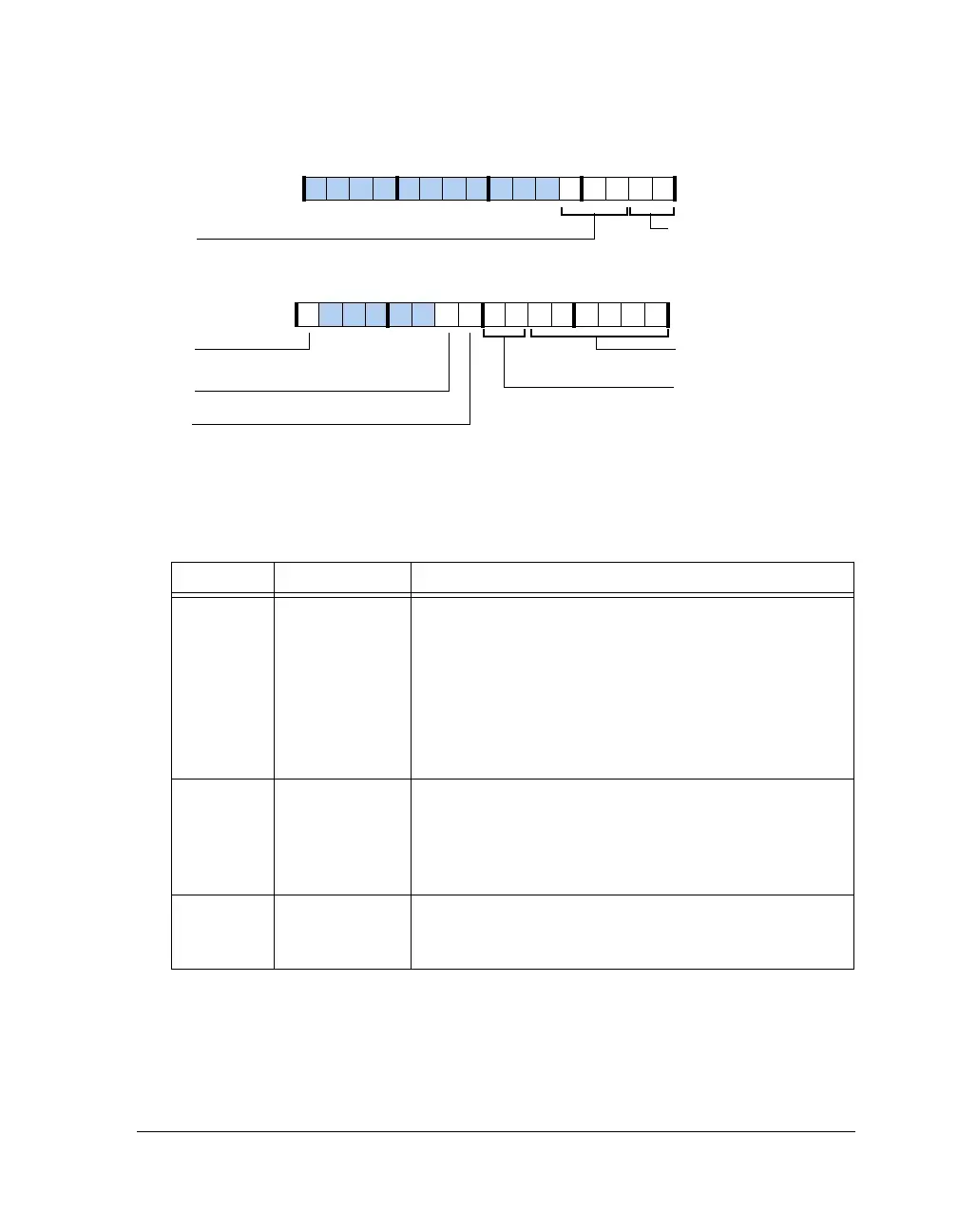
Figure A-4. PMCTL Register
Table A-5. PMCTL Register Bit Descriptions (RW)
Bit Name Description
5–0 PLLM PLL Multiplier.
PLLM = 0 PLL multiplier = 128
0<PLLM<63 PLL multiplier = 2 × PLLM
Reset value = CLK_CFG1–0
00 = 001000 = 8x
01 = 100000 = 32x
10 = 010000 = 16x
11 = 001000 = 8x
7–6 PLLD PLL Divider (Output Clock Post Divider).
00 = clock divider = 2
01 = clock divider = 4
10 = clock divider = 8
11 = clock divider = 16
8INDIVPLL Input Clock Pre Divider.
0 = Divide by 1
1 = Divide by 2
PLLBP
DIVEN
CRAT (17–16)
PLL Clock Ratio
PLLM (5–0)
PLL Multiplier
PLL Divider Enable
PLLD (7–6)
PLL Divider
INDIV
Input Divider
PLL Bypass
SDCKR
Core Clock to SDRAM Clock
31 302928 27 26 25 24 23 22 21 20 19 18 17 16
09 837564 2114 12 11 101315

 Loading...

