ADSP-214xx SHARC Processor Hardware Reference A-103
Registers Reference
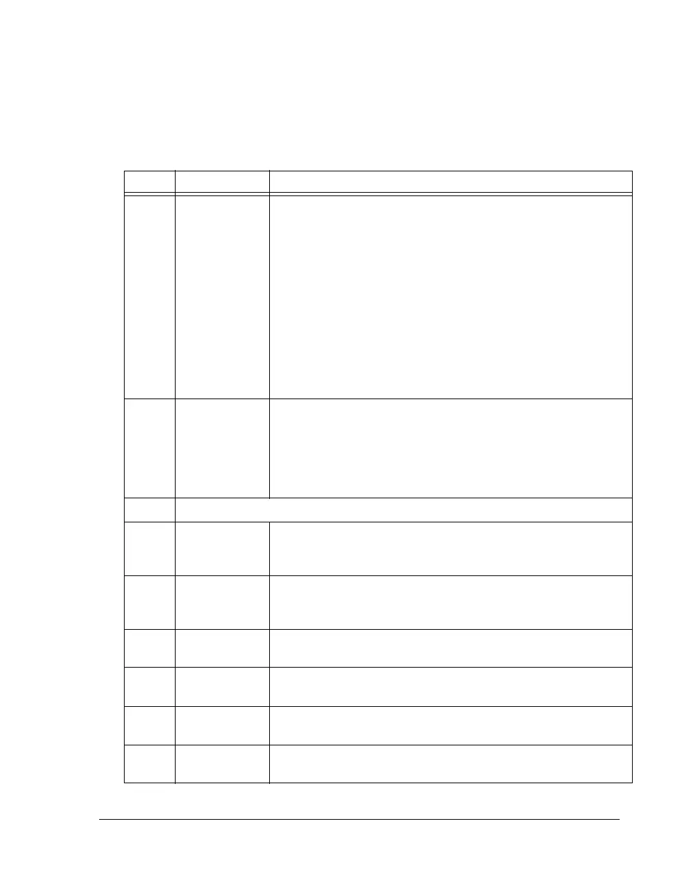
Table A-66. MLB_CECRx Register Bit Descriptions for Asynchronous
and Control Channels (RW)
Bit Name Description
7–0 CA Channel Address. These bits determine the channel address associated
with this logical channel. MLB channel address is 16 bits; bits 15–9
and LSB are always zero. Only bits 8–1 vary and they are defined by
MLB_CECRx bits 7–0.
Channel Address
00000001 0x0002
00000010 0x0004
00000011 0x0006
00000100 0x0008
.............
11111111 0x01FE
For further information on assigning the device address, refer to the
MLB specification.
12–8 PCTH Packet Count Threshold, I/O Mode. Software can program this field
with the number of packets to receive before generating an Rx
packet-count service request. This service request is generated indepen-
dent of, and in addition to, other service requests generated via the
standard buffer threshold mechanism. In DMA mode these bits are
reserved.
15–13 Reserved
16 MASK0 Mask Protocol Error. When set, masks protocol error channel inter-
rupts for this logical channel. This bit valid for all Rx channel types.
This is valid for asynchronous and control Tx channels only.
17 MASK1 Mask Detect Break. When set, masks detect break channel interrupt
for this logical channel. This bit is valid for asynchronous and control
channels only.
18 MASK2 (I/O) Masks Receive Service Request. When set, masks Rx channel service
request interrupts for this logical channel.
18 MASK2 (DMA) Mask Buffer Done. When set, masks buffer done channel interrupts
for this logical channel.
19 MASK3 (I/O) Masks Transmit Service Request. When set, masks Tx channel service
request interrupts for this logical channel.
19 MASK3 (DMA) Mask Buffer Start. When set, masks buffer start channel interrupts for
this logical channel.

 Loading...

