ADSP-214xx SHARC Processor Hardware Reference A-153
Registers Reference
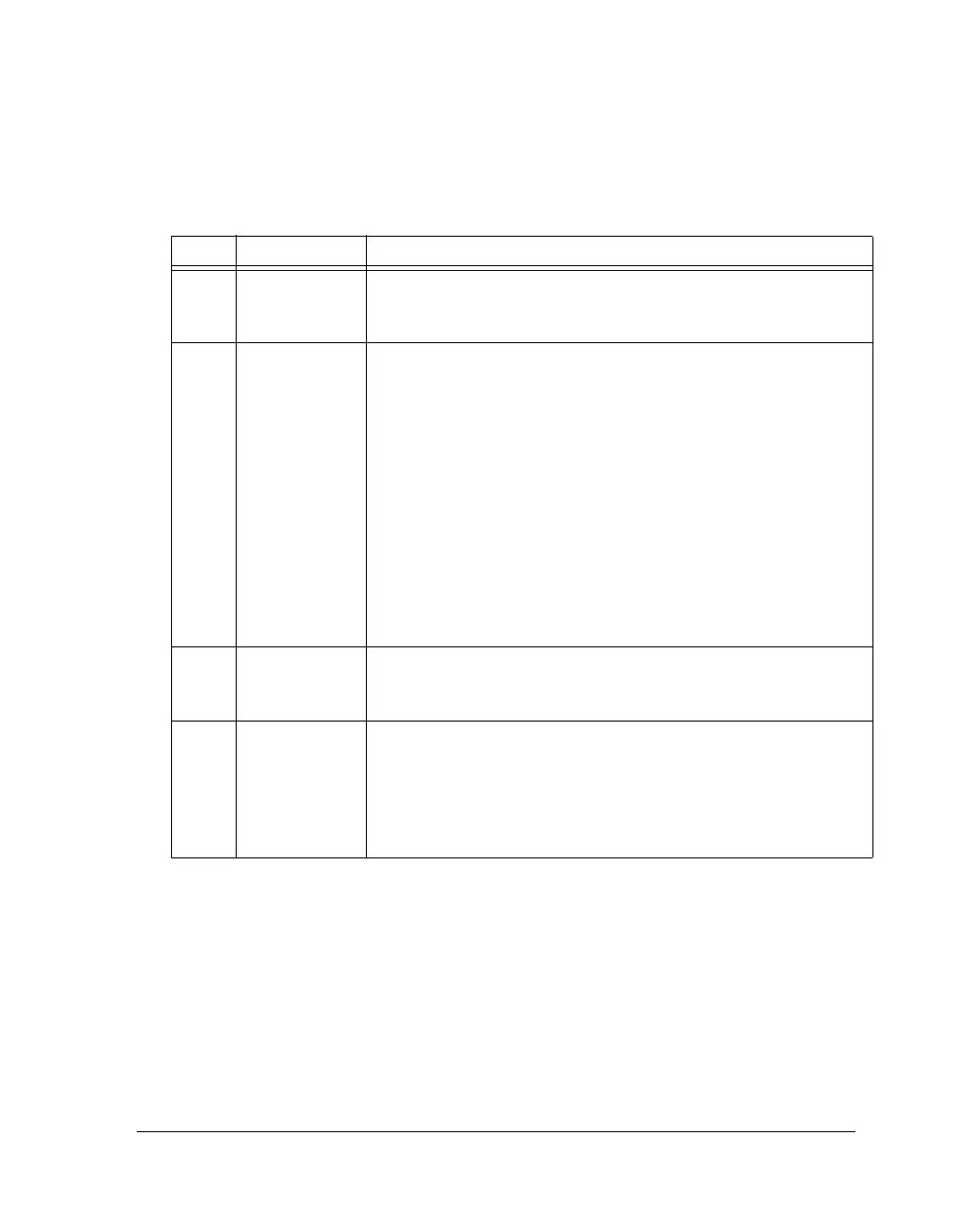
Table A-84. SPCTLx Register Bit Descriptions (Standard Serial Mode)
(RW)
Bit Name Description
0SPEN_A Enable Channel A Serial Port.
0 = Serial port A channel disabled
1 = Serial port A channel enabled
2–1 DTYPE Data Type Select. Selects the data type formatting for standard serial
mode transmissions. For standard serial mode A channels, selection of
companding mode and MSB format are exclusive:
Serial Data Channel A Type Formatting
00 Right-justify, zero-fill unused MSBs
01 Right-justify, sign-extend unused MSBs
10 Compand using μ-law
11 Compand using A-law
Serial Data Channel B Type Formatting
For Standard serial mode B channels, companding mode is unavailable.
0 Right-justify, zero-fill unused MSBs
1 Right-justify, sign-extend unused MSBs
The transmit buffer does not zero-fill or sign-extend transmit data
words; this only takes place for the receive buffer.
3LSBF Serial Word Endian Select.
0 = Big endian (MSB first)
1 = Little endian (LSB first)
8–4 SLEN Serial Word Length Select. Selects the word length in bits. The value of
SLEN = serial word length. For DSP standard mode, word sizes can
range from 3 bit (SLEN = 3) to 32 bits (SLEN = 32).
Do not set the SLEN less then 3. Words smaller than 32 bits are
right-justified in the receive and transmit buffers, residing in the least
significant (LSB) bit positions.
 Loading...


