ADSP-214xx SHARC Processor Hardware Reference 16-13
Peripheral Timers
registers are read-only in WDTH_CAP mode. The period and pulse width
measurements are with respect to a clock frequency of
PCLK ÷ 2.
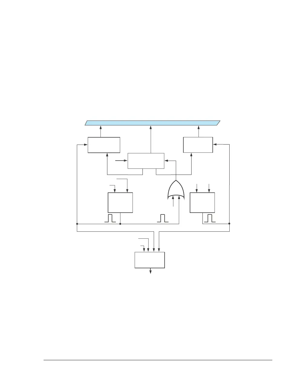
Figure 16-5 shows a flow diagram for WDTH_CAP mode. In this mode,
the timer resets words of the count in the TMxCNT register value to
0x0000 0001 and does not start counting until it detects the leading edge
on the TIMERx_I signal.
When the timer detects a first leading edge, it starts incrementing. When
it detects the trailing edge of a waveform, the timer captures the current
value of the count register (= TMxCNT ÷ 2) and transfers it into the TMxW
width registers. At the next leading edge, the timer transfers the current
value of the count register (= TMxCNT ÷ 2) into the TMxPRD period register.
Figure 16-5. Timer Flow Diagram – WDTH_CAP Mode
PCLK
TIMER_ENABLE
RESET
INTERRUPT
PERIOD_CNT
INTERRUPT
LOGIC
PULSE
TMxOVF
PULSE TIMERx_I
TRAILING
EDGE
DETECT
CORE BUS
LEADING
EDGE
DETECT
TIMERx_COUNTER
TIMERx_WIDTHTIMERx_PERIOD
TIMERx_I

 Loading...

