ADSP-214xx SHARC Processor Hardware Reference A-159
Registers Reference
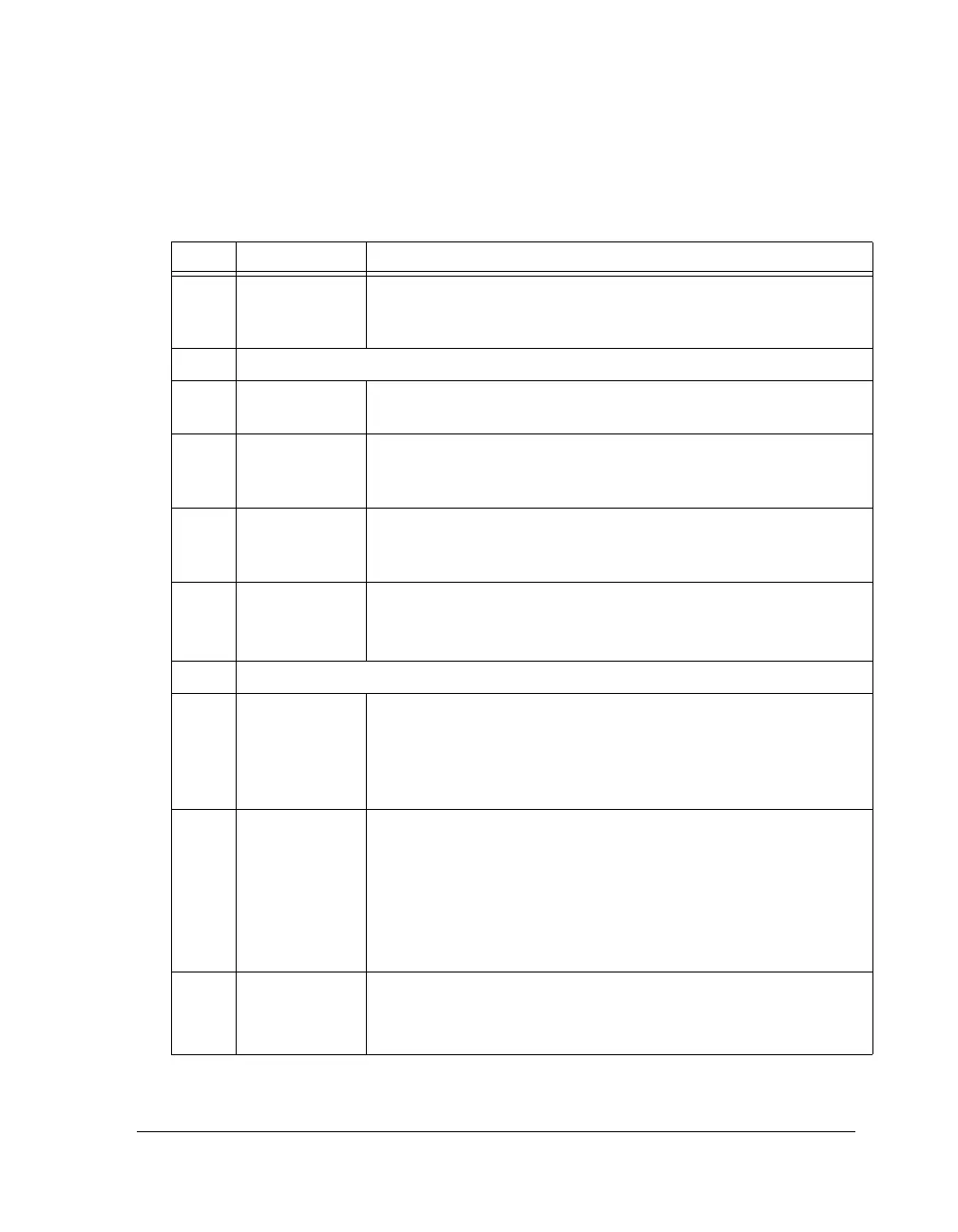
Table A-85. SPCTLx Register Bit Descriptions (I
2
S,
Left-Justified) (RW)
Bit Name Description
0SPEN_A Enable Channel A Serial Port.
0 = Serial port A channel disabled
1 = Serial port A channel enabled
3–1 Reserved
8–4 SLEN Serial Word Length Select. Selects the word length in bits. Word sizes
can be from 8 bits to 32 bits.
9PACK 16-Bit to 32-Bit Word Packing Enable.
0 = Disable 16- to 32-bit word packing
1 = Enable 16- to 32-bit word packing
10 MSTR Master Clock Select.
0 = Select external clock and WS
1 = Select internal clock and WS
11 OPMODE Sport Operation Mode.
1 = Selects the I
2
S or left-justified mode.
Bit 17 is used to select either of both modes.
14–12 Reserved
15 DIFS Data Independent Frame Sync Select.
0 = Serial port uses a data-dependent frame sync (sync when TX FIFO
is not empty or when RX FIFO is not full).
1 = Serial port uses a data-independent frame sync (sync at selected
interval)
16 L_FIRST Frame Sync Channel First Select. Selects left or right channel word first
after valid edge of frame sync. For left-justified mode channel order:
0 = first data after the rising edge
1 = first data after the falling edge
For I
2
S mode channel order:
0 = first data after the falling edge
1 = first data after the rising edge
17 OPMODE
(LAFS)
Operation Mode (I
2
S or Left-Justified Mode Select).
0 = I
2
S mode
1 = Left-justified mode

 Loading...

