Peripherals Routed Through the DAI
A-164 ADSP-214xx SHARC Processor Hardware Reference
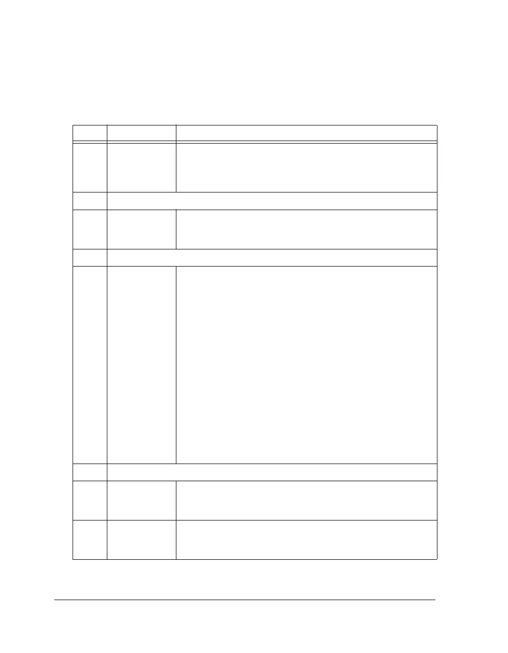
12 CKRE Clock Rising Edge Select. Determines clock signal to sample data
and the frame sync selection.
0 = Falling edge
1 = Rising edge
13 Reserved
14 IMFS Internal Multichannel Frame Sync Select. Selects whether the serial
port uses an internally generated frame sync (if set, = 1) or uses an
external frame sync (if cleared, = 0).
15 Reserved
16 LMFS/L_FIRST Active Multichannel Frame Sync/Channel Order First. For multi-
channel mode this bit (LMFS) selects the logic level of the (transmit
or receive) frame sync signals.
0 = Active HIGH level frame sync
1 = Active LOW level frame sync
If FSED bit in SPCTLNx register is high (=1) the SPORTs detects an
active edge of an external frame sync and starts transmitting/receiving
only after that (even if you enable SPORTs at any instant of active
frame sync). This is done only when SPORTs are programmed for
external FS mode (IMFS = 0). If FSED bit is cleared (reset value),
SPORTs behaves similar to previous SHARC processors.
For packed mode, this bit (L_FIRST) selects left or right channel
word first after valid edge.
0 = Tx/Rx on right channel first
1 = Tx/Rx on left channel first
17 Reserved
18 SDEN_A Enable Channel A Serial Port DMA.
0 = Disable serial port channel A DMA
1 = Enable serial port channel A DMA
19 SCHEN_A Enable Channel A Serial Port DMA Chaining.
0 = Disable serial port channel A DMA chaining
1 = Enable serial port channel A DMA chaining
Table A-86. SPCTLx Register Bit Descriptions (Packed and Multichannel)
(RW) (Cont’d)
Bit Name Description

 Loading...

