Internal control/status words
Function Diagrams
2-1193
© Siemens AG 2007 All Rights Reserved
SINAMICS S List Manual (LH1), 07/2007
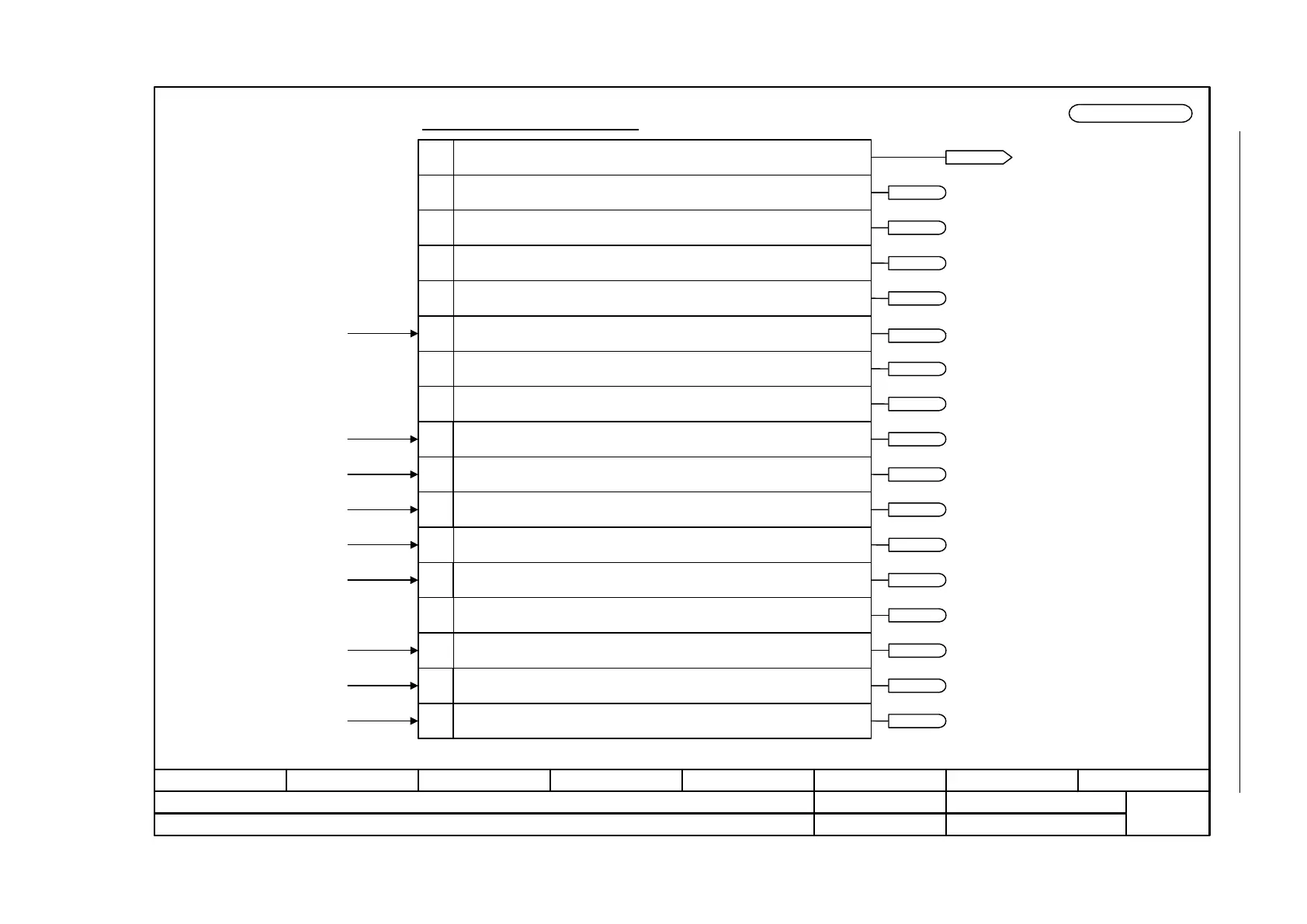
Figure 2-84 2526 – Status word, closed-loop control
- 2526 -
Function diagram
87654321
fp_2526_01_eng.vsd
DO: SERVO, VECTOR
SINAMICS S
13.02.07 V02.05.00
Internal control/status words - Status word, closed-loop control
1
2
4
1 = Initialization completed
Meaning
1 = De-magnetization completed
1 = Pulses enabled
1 = Magnetization completed
1 = Frequency, negative
0
Bit No.
7
Status word closed-loop control
8
9
11
1 = Field weakening active
1 = Voltage limit active
1 = Frequency limit active
1 = Vdc_max controller active14
1 = Vdc_min controller active15
r0056
ZSW closed-loop control
r0056.11
r0056.14
r0056.15
r0056.0
r0056.1
r0056.2
r0056.4
r0056.7
r0056.8
r0056.9
3 1 = Soft starting available
r0056.3
5 Reserved
r0056.5
6 1 = Acceleration voltage active
r0056.6
12 1 = Current limiting controller, voltage output active
r0056.12
13 1 = Current/torque limiting active r0056.13
10 1 = Slip limiting active r0056.10
Refer to [1020.7]
p0115[y] (Motor Modules)
<1>
<1>
<1>
<1>
<1>
<1> Only for V/f control.
<2> Not for SERVO.
<2>
<2>
<2>
<2>
<2>
<2>
<2>
<2>
<2>
<2>
[6722.6][6725.6]
[6725.4][6730.5][6731.5][6732.4]
[6722.3][6725.4]
[6714.8]
[6730.5][6731.5][6732.4]
[6220.8][6320.8]
[6220.8][6320.8]
[6310.8]
[6060.7]
[6710.2]
[6031.6][6710.2]
[8012.5]
[8018.1]
[2701.1][2707.1]

 Loading...


