Function Diagrams
Signals and monitoring functions
2-1330
© Siemens AG 2007 All Rights Reserved
SINAMICS S List Manual (LH1), 07/2007
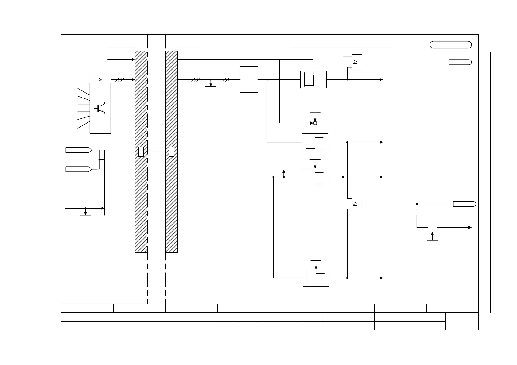
Figure 2-208 8014 – Thermal monitoring, power unit
Control Unit
DRIVE-
CLiQ
Power unit
Temperature measurement
- 8014 -
Function diagram
87654321
fp_8014_01_eng.vsd
DO: A_INF, B_INF, S_INF, SERVO, VECTOR
SINAMICS S
04.07.07 V02.05.00
Signals and monitoring functions - Thermal monitoring, power unit
Tmax heatsink
Thermal monitoring for the power unit
Max
0
1
0
1
Power unit
temperatures [°C]
r0037 [0...19]
Maximum power unit temperature
5 °C
Faults "power unit overtemperature"
F30004 inverter heatsink
F30025 chip F30035 air intake
F30036 electronics module
F30037 rectifier
1 = Fault thermal overload in power unit
1 = Alarm, thermal overload, power unit
+
-
0
1
Alarms "power unit overtemperature"
A05000 inverter heatsink
A05001 chip
A05002 air intake
A05003 electronics module
A05004 rectifier
F30005 "Power unit overload"
Overload response
Power unit overload response
p0290
<1>
Power unit overload
(0...100 %)
r0036
[2548.2]
0
1
A07805 "Power unit overload"
Alarm threshold
i²t overload power unit 0...100 %
p0294 (95 %)
100 %
p0115[3] (2000.00 µs)
1
1
LT I_rated
r0207
i²t model
power unit
r2135.13
r2135.15
[2548.2]
<1> Not for A_INF, B_INF and S_INF.
<2> Not for Basic Line Modules Chassis.
r0068
I_act abs. value
[5730.4]
[8850.4]
[8950.4]
r0068[0]
I_act abs. value
[6714.5]
<2>
<2>
<2>
<2>
<2>
<2>
<2>
<2>

 Loading...


