Terminal Module 41 (TM41)
Function Diagrams
2-1405
© Siemens AG 2007 All Rights Reserved
SINAMICS S List Manual (LH1), 07/2007
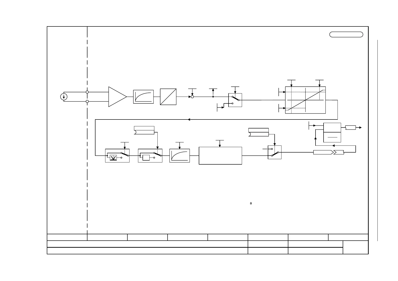
Figure 2-272 9663 – Analog input (AI 0)
- 9663 -
Function diagram
87654321
fp_9663_51_eng.vsd
DO: TM41
SINAMICS
07.12.06 V02.05.00
Terminal Module 41 (TM41) - Analog input (AI 0)
AI 0
scaling
r4055[0]
p4069 [0]
(1)
Enable
Hardware smoothing
100 µs
p4066 [0]
(0)
p4067 [0]
y = x if
|y - x| > p4068
otherwise y = y(old)
y
x
A
D
Offset
-20.000...20.000
p4063[0] (0.000)
-11.000...11.000
p4057[0] (0.000)
-11.000...11.000
p4059[0] (10.000)
[V]
r4052[0]
p4097[0]
-1000.00...1000.00 %
p4060[0] (100.00)
-1000.00...1000.00 %
p4058[0] (0.00)
X523.1
X523.2
+
-
0 %
Smoothing
0.0...1 000.0 ms
p4053[0] (0.0)
Window to suppress noise
0.00...20.00 %
p4068[0] (0.00)
[%]
1
0
<1>
+
+
-11...+11 V
xy
Reference quantities
p200x
y
x
2
x
1
x
100%
xx
21
•
<2>
x
1
y
2
x
2
y
1
y
x
[%]
[V]
-1
0
1
0
1
<4> If the PROFIdrive communication is operated with clock cycle synchronism (r2064[0] = 1), the time slice automatically adjusts to the PROFIdrive
clock cycle (r2064[1]). When the PROFIdrive interface is in this mode, p4099 does not influence the time slice for TM41.
<3> Caution:
The voltage between an input and ground must not exceed 35 V.
The voltage between the inputs must not exceed 35 V.
1
0
<3>
p4099[1] (4000.00 µs)
<4>
<1> When interconnected, the output signals are referred to the reference quantities p200x or p205x (100% p20xx).
<2> Differential inputs!
For input signals referred to ground, terminal 2 or 4 must be connected to reference potential M.
Simulation mode
-20.000...20.000
p4098[0] (0.000)

 Loading...


