Servo control
Function Diagrams
2-1285
© Siemens AG 2007 All Rights Reserved
SINAMICS S List Manual (LH1), 07/2007
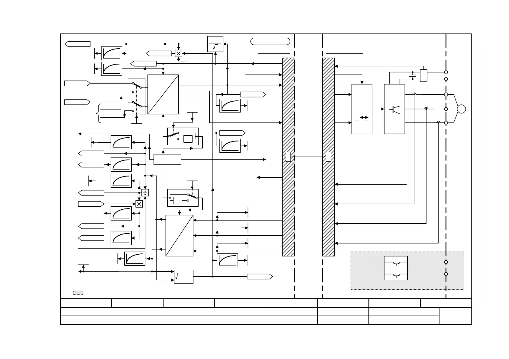
Figure 2-167 5730 – Interface to the Motor Module (control signals, current actual values)
- 5730 -
Function diagram
87654321
fp_5730_01_eng.vsd
DO: SERVO
SINAMICS S
15.05.07 V02.05.00
Servo control - Interface to the Motor Module (gating signals, current actual values)
Motor model
0
P
2
3
r1733
Quad V set
Voltage angle
+
Coordinate converter
and transformation
Phase current actual value
IW
IV
IU
Control Unit
DRIVE-CLiQ
PWM
Motor Module
M
~
+
–
U
V
W
r0078[0]
Iq_act
r1732
Direct V set
[5714.8]
[5714.8]
M2Iq torque factor
i_max_MM
DC link voltage
r0074
Modulat depth
Uq_set_3
Ud_set_3
From V/f control
[5300.8]
<1> Iq = M2Iq x M (M2Iq = "Torque-To-Iq factor").
<1>
+ BRP
-BRN
Brake control
P24
M
<3> The voltage angle is the angle of the voltage vector in a fixed stator coordinate system.
<3>
Vdc smooth
r0026
Modulat depth
smth
r0028
f_outp smooth
r0024
r0066
f_outp
U_outp smooth
r0025
Iq_act smooth
r0030
M_act smooth
r0031
p0115[0] (125.00 µs)
22
idiq
I_act abs val smth
r0027
Id_act smooth
r0029
M2Iq
Maximum current, Motor Module
<2> i_max_MM depends on the power unit temperature.
<2>
Pulse enable via
hardware
Pulse enable via
hardware
P_stall
[5640.1]
[2701.8]
[2711.8]
[5722.4]
[5640.4]
[5714.2]
[5730.2]
<4>
Additionally for Booksize format.
<4>
K
1
0
1
[5714.4]
[5730.4]
[5714.4]
100 ms
100 ms
100 ms
100 ms
100 ms
100 ms
100 ms
x
1
x
2
2
xx
21
x
100 ms
P_active_actual smth
r0032
100 ms
[5300.7]
r0063
n_act smooth
1.5 x cos phi
r0082[1]
Smoothed with p0045
Coordinate
converter
and trans-
form-
ation
r0082[0]
Unsmoothed
r0072
U_output
r0068
I_act abs value
r0082[2]
Power drawn
Vf diagn act
p1317
p0045
r0078[1]
Iq_act
Transformation angle
r0070
Vdc_act
p0045
[7017.6]
[8014.1]
r0080
M_act
Id_act
r0076
Phase W
r0069[2]
Phase V
r0069[1]
Phase U
r0069[0]
Dir rev rot field
p1821[D]
-1
0
1
Dir rev rot field
p1821[D]
-1
0
1
+
–
Transformation angle

 Loading...


