Function Diagrams
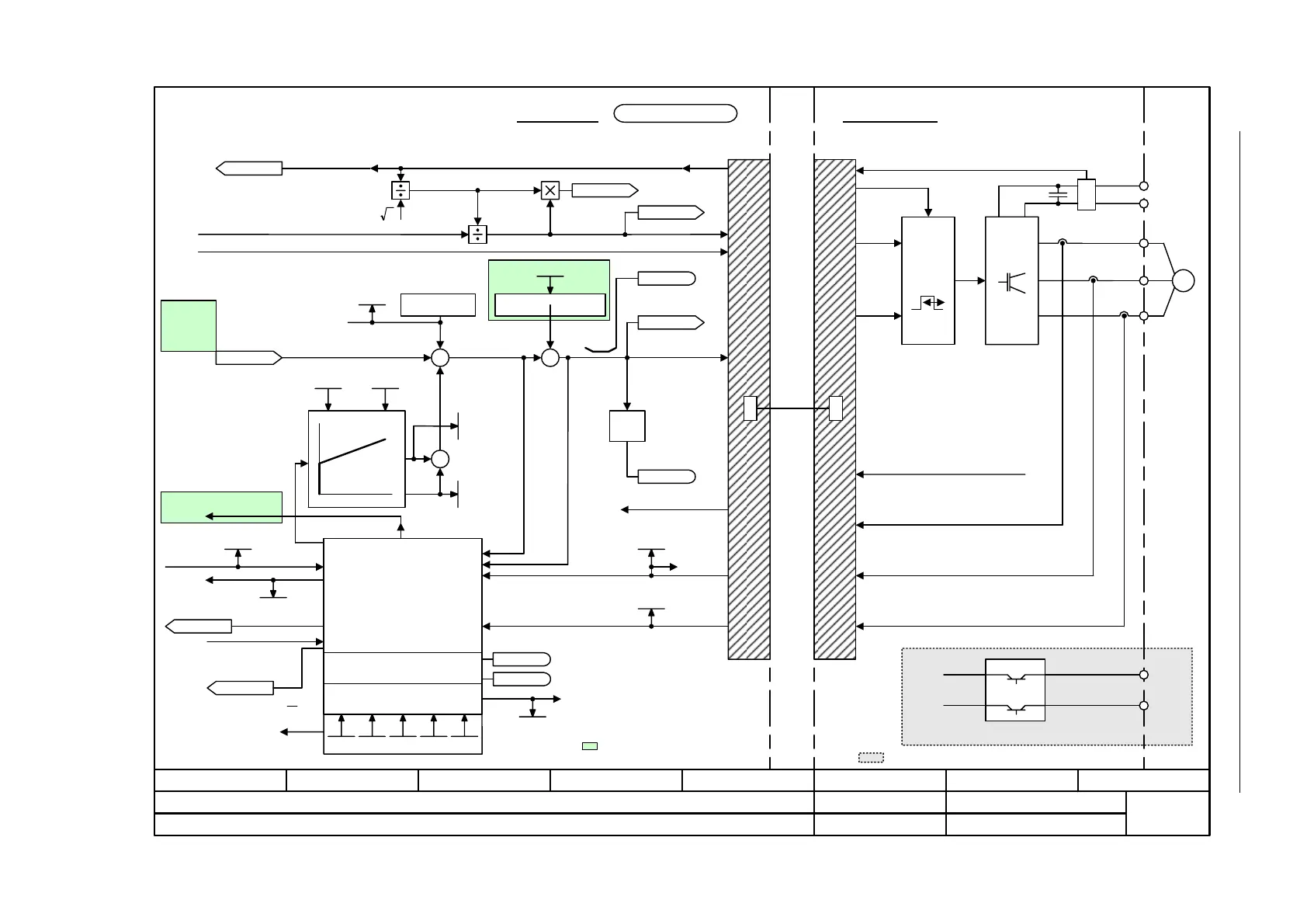
Vector control
2-1310
© Siemens AG 2007 All Rights Reserved
SINAMICS S List Manual (LH1), 07/2007
Figure 2-191 6730 – Interface to Motor Module (ASM, p0300 = 1)
[6723.1]
[6799.1]
<1>
Precontrol
speed
[6030.8]
- 6730 -
Function diagram
87654321
fp_6730_01_eng.vsd
DO: VECTOR
SINAMICS S
23.03.07 V02.05.00
Vector control - Interface to the Motor Module (ASM, p0300 = 1)
Model control
p1750 ... p1759
Motor model
(observer)
r1762, r1763,
r1778, r1779
Control Unit
DRIVE
CLiQ
PWM
Motor Module
M
~
+
–
U
V
W
r0084
Flux actual value
DC link voltage
+ BRP
-BRN
Brake control
P24
M
I_max Motor Module
Pulse enable
HW
p1750 p1755 p1756 p1758
Kp Tn
p1760
p1764
p1761
p1767
r0070
Vdc_act
r0074
Modulation depth
Adaptation controller
n_act calculation
2
U_set
U_angle
Current model
I_max Motor Module
Vibration damping
p1740
r0066
f_outp
[4715.6]
p1759
[1690.1]
[6640.1]
[4715.4]
Iq
M
= Only for vector ctrl. without encoder.
= Only for vector ctrl. with encoder.
<1>
Sign +
or -
Frequency, negative
r0056.7
Frequency limit active
r0056.11
R1751
MotMod status
MotMod
n_adapt Kp
r1770
MotMod
n_adapt Tn
r1771
R_stator act
r0395
[6722.7]
Stall monitoring
p1744, p1745
r1408.11
r1408.12
<2>
[6714.1]
<2>
<1>
<1>
[6310.1]
[6799.1]
[6310.5]
[6640.5]
[6710.2]
[6714.6]
[6714.1]
+
+
+
+
+
+
+
f_slip
r0065
r0063[0]
n_act
<3> Additionally for Booksize
<3> [8012.3]
[8012.3]
[1690.8]
[6714.8]
[6714.8]
Refer to [1020.7]
p0115[y] (Motor Modules)
[6799.1]
[6714.5]
r0072
U_output
[6799.1]
[6799.1]
[6714.4]
cos phi actual value
r0087
I_Phase actual value
r0069[0...2]
U_Phase actual value
r0089[0...2]
r0094
Transformat_angle
Dir rev rot field p1821[D]
[4715.7]
[2526.2]

 Loading...


