Signals and monitoring functions
Function Diagrams
2-1331
© Siemens AG 2007 All Rights Reserved
SINAMICS S List Manual (LH1), 07/2007
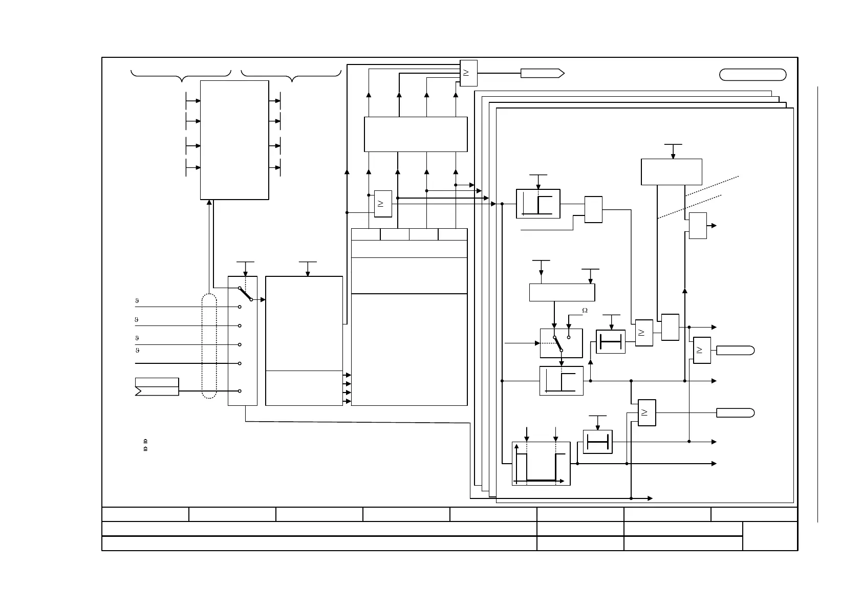
Figure 2-209 8016 – Thermal monitoring, motor
- 8016 -
Function diagram
87654321
fp_8016_01_eng.vsd
DO: SERVO, VECTOR
SINAMICS S
19.07.07 V02.05.01
Signals and monitoring functions - Thermal monitoring, motor
Mot T_environment
p0625[M]
Thermal
3-mass-model
(for induction motors
only)
Rated motor temperature rise
MotTMod T_environ
r0630
Calculated motor temperatures
Mot temperature [°C]
(0)
p0603[C]
from encoder 2
Mot temp_sensortyp
p0601[M]
Model tracking
Nur
bei
KTY
[4704.8]
from Motor Modules
or CUA31
from encoder 3
[4704.8]
from encoder 1
[4704.8]
Mot T_on iron
p0626[M]
Mot T_on stator
p0627[M]
Mot T_on rotor
p0628[M]
MotTMod T_iron
r0631
MotTMod T_copper
r0632
MotTMod T_rotor
r0633
1 = PTC alarm and time
3 = KTY84 & PTC, for
encoder only
2 = KTY84
0 = No sensor
10 = Evaluation of
several temperature
channels
Mot temp_sensor
p0600[M]
0
1
11
3
2
10
1.00 s
r4620[0]
r4620[1]
r4620[2]
r4620[3]
r0035
T_mot gemessen
30 = Bimetal NC contact fault
12 = PTC alarm and time step
32 = Bimetal NC contact fault/
alarm with time step
31 = Bimetal NC contact alarm
0 = no sensor
11 = PTC alarm
Configuration
Mot temp_senstyp
T0
&
&
1
p0606[M]
A07910
"Motor overtemperature"
F07011
"Motor overtemperature"
<1>
Fault response
I_max reduction
[1690.1][6640.2]
p0610[M]
p0610 = 0: No response, only alarm, no reduction of I_max
p0610 = 1: Alarm and reduction of I_max and fault (F07011)
p0610 = 2: Alarm and fault (F07011), no reduction of I_max
p0610 = 1
Suppress fault
p0610 = 0
[2548.2]
r2135.14
A07820 "Temperature sensor not connected"
A07015
"Motor temperature
sensor fault alarm"
A07016
"Motor temperature
sensor fault, fault"
-140 °C 250 °C
Mot temp_sens time
p0607[M]
<2>
0
1
Mot temp fault thresh
p0605[M]
&
KTY sensor type
(threshold not applicable for PTC)
<4>
1
1
[2548.2]r2135.12
T0
<5>
KTY PTC
Sensor type
Mot TempAlrmThresh
p0604[M]
0
1
<3>
M I N
Mot temp alarm 1
p0616[M]
<6>
1650
1
MAX
10 = PTC fault
[9576.3]
4 = Bimetal NC contact
alarm with time step
for MM only
1
<1> For KTY and PTC, the value p0606 = 0 has a different meaning:
KTY: 0 The output of the timer is always switched out (logical 0)
PTC: 0 Delay time = 0 s
<2> As for the switch-in delay, refer to [1024]. p0607 = 0 suppresses fault F07016.
<3> For KTY and "No sensor", temperature as defined in the model.
<4> Applies only for VECTOR.
<5> P0606 does not work for alarms via p0616.
<6> The relevant rated response temperature in °C depends on the temperature sensor chosen by the motor manufacturer.
<7> The assignment of temperature channels T1...T4 depends on the hardware used.
e.g. r4105 from TM31
Temp.
channel
1
Temp.
channel
2
Temp.
channel
3
Temp.
channel
4
20 = KTY84
p4600[E] p4601[E] p4602[E] p4603[E]

 Loading...


