Touchscreen Controller Registers
www.ti.com
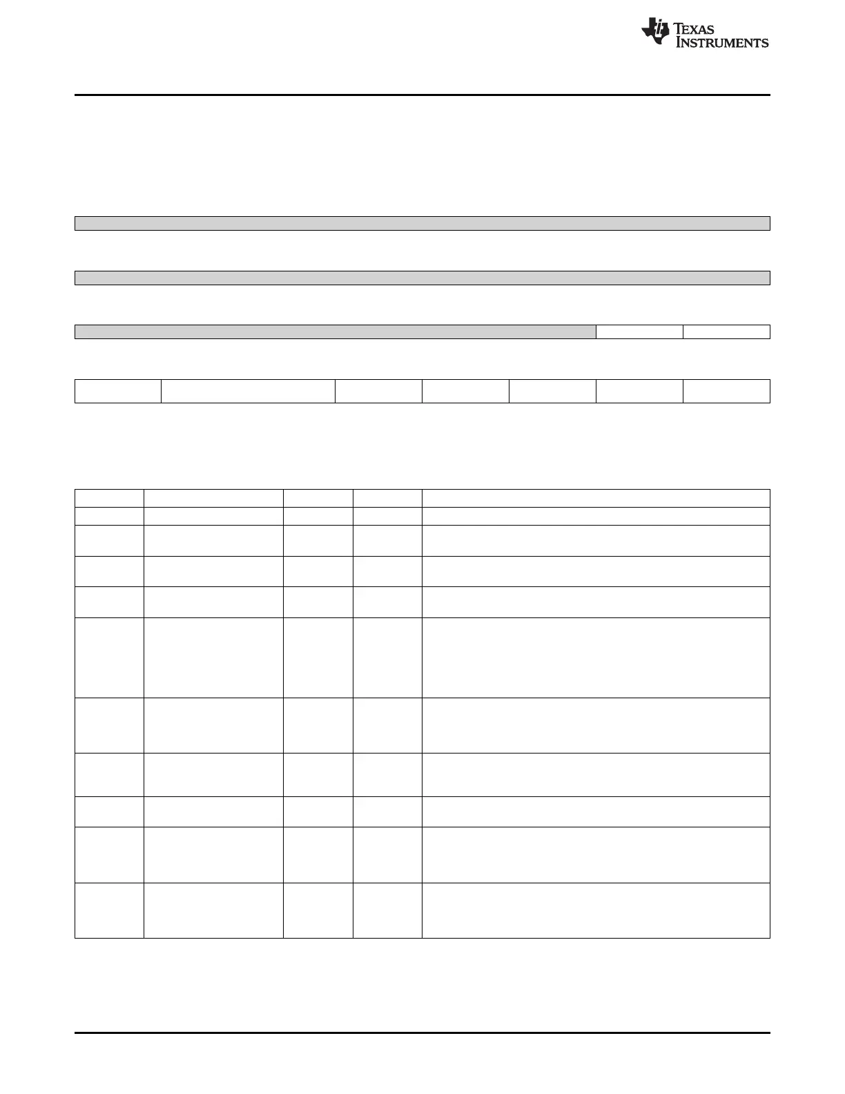
12.5.1.10 CTRL Register (offset = 40h) [reset = 0h]
CTRL is shown in Figure 12-14 and described in Table 12-14.
@TSC_ADC_SS Control Register
Figure 12-14. CTRL Register
31 30 29 28 27 26 25 24
Reserved
R-0h
23 22 21 20 19 18 17 16
Reserved
R-0h
15 14 13 12 11 10 9 8
Reserved HW_preempt HW_event_mapping
R-0h R/W-0h R/W-0h
7 6 5 4 3 2 1 0
Touch_Screen_Enabl AFE_Pen_Ctrl Power_Down ADC_Bias_Select StepConfig_WriteProt Step_ID_tag Enable
e ect_n_active_low
R/W-0h R/W-0h R/W-0h R/W-0h R/W-0h R/W-0h R/W-0h
LEGEND: R/W = Read/Write; R = Read only; W1toCl = Write 1 to clear bit; -n = value after reset
Table 12-14. CTRL Register Field Descriptions
Bit Field Type Reset Description
31-10 Reserved R 0h
9 HW_preempt R/W 0h 0 = SW steps are not pre-empted by HW events.
1 = SW steps are pre-empted by HW events
8 HW_event_mapping R/W 0h 0 = Map HW event to Pen touch irq (from AFE).
1 = Map HW event to HW event input.
7 Touch_Screen_Enable R/W 0h 0 = Touchscreen transistors disabled.
1 = Touchscreen transistors enabled
6-5 AFE_Pen_Ctrl R/W 0h These two bits are sent directly to the AFE Pen Ctrl inputs.
Bit 6 controls the Wiper touch (5 wire modes)Bit 5 controls the X+
touch (4 wire modes)User also needs to make sure the ground path
is connected properly for pen interrupt to occur (using the
StepConfig registers)Refer to section 4 interrupts for more
information
4 Power_Down R/W 0h ADC Power Down control.
0 = AFE is powered up (default).
1 = Write 1 to power down AFE (the tsc_adc_ss enable (bit 0)
should also be set to off)
3 ADC_Bias_Select R/W 0h Select Bias to AFE.
0 = Internal.
1 = Reserved.
2 StepConfig_WriteProtect_ R/W 0h 0 = Step configuration registers are protected (not writable).
n_active_low 1 = Step configuration registers are not protected (writable).
1 Step_ID_tag R/W 0h Writing 1 to this bit will store the Step ID number with the captured
ADC data in the FIFO.
0 = Write zeroes.
1 = Store the channel ID tag.
0 Enable R/W 0h TSC_ADC_SS module enable bit.
After programming all the steps and configuration registers, write a
1to this bit to turn on TSC_ADC_SS.
Writing a 0 will disable the module (after the current conversion).
1048
Touchscreen Controller SPRUH73H–October 2011–Revised April 2013
Submit Documentation Feedback
Copyright © 2011–2013, Texas Instruments Incorporated

 Loading...


