www.ti.com
UART Registers
19.5.1.19 Mode Definition Register 1 (MDR1)
The mode of operation is programmed by writing to MDR1[2:0]; therefore, the mode definition register 1
(MDR1) must be programmed on startup after configuration of the configuration registers (DLL, DLH, and
LCR). The value of MDR1[2:0] must not be changed again during normal operation. The mode definition
register 1 (MDR1) is shown in Figure 19-52 and described in Table 19-50.
NOTE: If the module is disabled by setting the MODESELECT field to 7h, interrupt requests can still
be generated unless disabled through the interrupt enable register (IER). In this case, UART
mode interrupts are visible. Reading the interrupt identification register (IIR) shows the UART
mode interrupt flags.
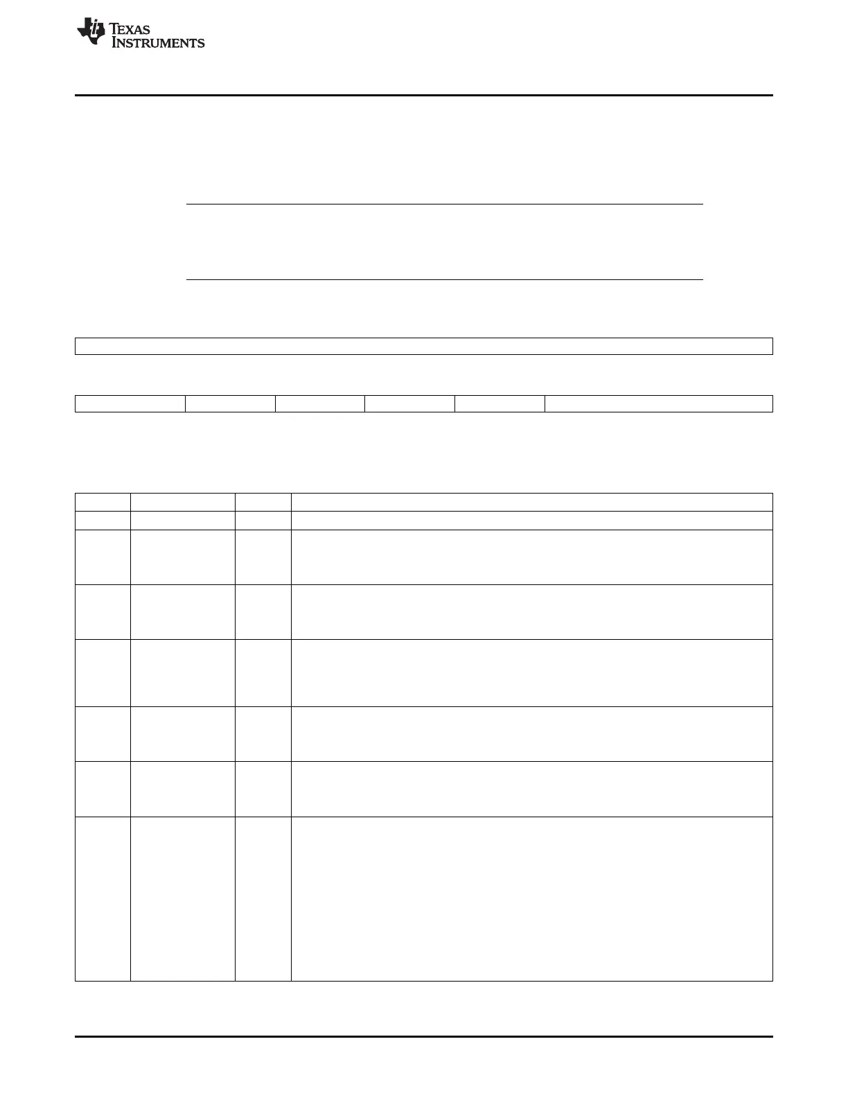
Figure 19-52. Mode Definition Register 1 (MDR1)
15 8
Reserved
R-0
7 6 5 4 3 2 0
FRAMEENDMODE SIPMODE SCT SETTXIR IRSLEEP MODESELECT
R/W-0 R/W-0 R/W-0 R/W-0 R/W-0 R/W-7h
LEGEND: R/W = Read/Write; R = Read only; -n = value after reset
Table 19-50. Mode Definition Register 1 (MDR1) Field Descriptions
Bit Field Value Description
15-8 Reserved 0 Reserved.
7 FRAMEENDMODE IrDA mode only.
0 Frame-length method.
1 Set EOT bit method.
6 SIPMODE MIR/FIR modes only.
0 Manual SIP mode: SIP is generated with the control of ACREG[3].
1 Automatic SIP mode: SIP is generated after each transmission.
5 SCT Store and control the transmission.
0 Starts the infrared transmission when a value is written to the THR register.
1 Starts the infrared transmission with the control of ACREG[2]. Note: Before starting any
transmission, there must be no reception ongoing.
4 SETTXIR Used to configure the infrared transceiver.
0 If MDR2[7] = 0, no action; if MDR2[7] = 1, TXIR pin output is forced low.
1 TXIR pin output is forced high (not dependant of MDR2[7] value).
3 IRSLEEP IrDA/CIR sleep mode.
0 IrDA/CIR sleep mode disabled.
1 IrDA/CIR sleep mode enabled.
2-0 MODESELECT 0-7h UART/IrDA/CIR mode selection.
0 UART 16× mode.
1 SIR mode.
2h UART 16× auto-baud.
3h UART 13× mode.
4h MIR mode.
5h FIR mode.
6h CIR mode.
7h Disable (default state).
3523
SPRUH73H–October 2011–Revised April 2013 Universal Asynchronous Receiver/Transmitter (UART)
Submit Documentation Feedback
Copyright © 2011–2013, Texas Instruments Incorporated

 Loading...


