Enhanced PWM (ePWM) Module
www.ti.com
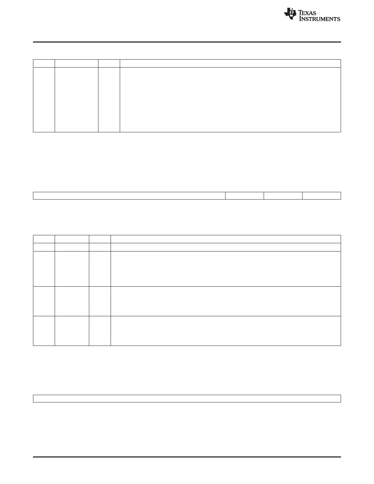
Table 15-60. Time-Base Control Register (TBCTL) Field Descriptions (continued)
Bit Field Value Description
1-0 CTRMODE 0-3h Counter Mode. The time-base counter mode is normally configured once and not changed during
normal operation. If you change the mode of the counter, the change will take effect at the next
TBCLK edge and the current counter value shall increment or decrement from the value before the
mode change.
These bits set the time-base counter mode of operation as follows:
0 Up-count mode
1h Down-count mode
2h Up-down-count mode
3h Stop-freeze counter operation (default on reset)
15.2.4.1.2 Time-Base Status Register (TBSTS)
The time-base status register (TBSTS) is shown in Figure 15-71 and described in Table 15-61.
Figure 15-71. Time-Base Status Register (TBSTS)
15 3 2 1 0
Reserved CTRMAX SYNCI CTRDIR
R-0 R/W1C-0 R/W1C-0 R-1
LEGEND: R/W = Read/Write; R/W1C = Read/Write 1 to clear; -n = value after reset
Table 15-61. Time-Base Status Register (TBSTS) Field Descriptions
Bit Field Value Description
15-3 Reserved 0 Reserved
2 CTRMAX Time-Base Counter Max Latched Status Bit
0 Reading a 0 indicates the time-base counter never reached its maximum value. Writing a 0 will have no
effect.
1 Reading a 1 on this bit indicates that the time-base counter reached the max value 0xFFFF. Writing a 1
to this bit will clear the latched event.
1 SYNCI Input Synchronization Latched Status Bit
0 Writing a 0 will have no effect. Reading a 0 indicates no external synchronization event has occurred.
1 Reading a 1 on this bit indicates that an external synchronization event has occurred (EPWMxSYNCI).
Writing a 1 to this bit will clear the latched event.
0 CTRDIR Time-Base Counter Direction Status Bit. At reset, the counter is frozen; therefore, this bit has no
meaning. To make this bit meaningful, you must first set the appropriate mode via TBCTL[CTRMODE].
0 Time-Base Counter is currently counting down.
1 Time-Base Counter is currently counting up.
15.2.4.1.3 Time-Base Phase Register (TBPHS)
The time-base phase register (TBPHS) is shown in Figure 15-72 and described in Table 15-62.
Figure 15-72. Time-Base Phase Register (TBPHS)
15 0
TBPHS
R/W-0
LEGEND: R/W = Read/Write; -n = value after reset
1584
Pulse-Width Modulation Subsystem (PWMSS) SPRUH73H–October 2011–Revised April 2013
Submit Documentation Feedback
Copyright © 2011–2013, Texas Instruments Incorporated

 Loading...


