www.ti.com
Multimedia Card Registers
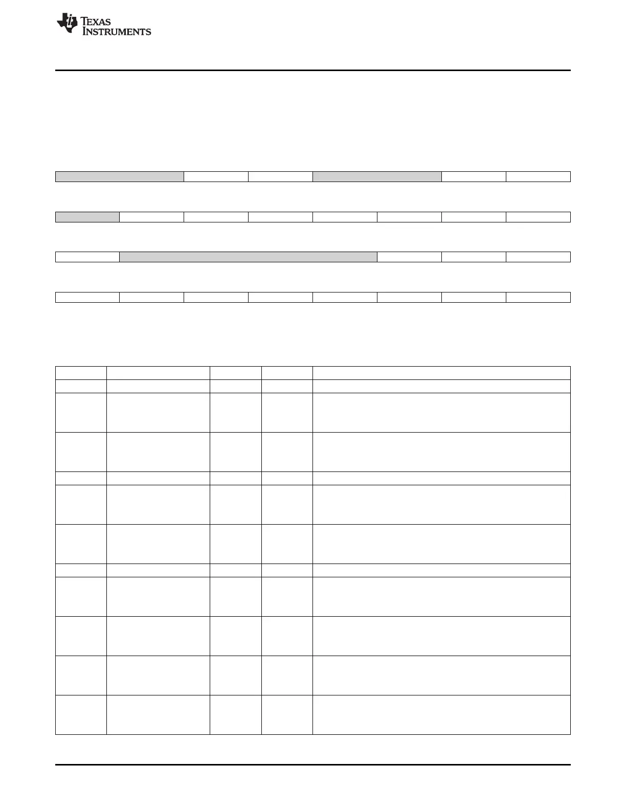
18.5.1.20 SD_IE Register (offset = 234h) [reset = 0h]
SD_IE is shown in Figure 18-56 and described in Table 18-39.
This register allows to enable/disable the module to set status bits, on an event-by-event basis.
SD_IE[31:16] = Error Interrupt Status Enable. SD_IE[15:0] = Normal Interrupt Status Enable.
Figure 18-56. SD_IE Register
31 30 29 28 27 26 25 24
Reserved BADA_ENABLE CERR_ENABLE Reserved ADMA_ENABLE ACE_ENABLE
R-0h R/W-0h R/W-0h R-0h R/W-0h R/W-0h
23 22 21 20 19 18 17 16
Reserved DEB_ENABLE DCRC_ENABLE DTO_ENABLE CIE_ENABLE CEB_ENABLE CCRC_ENABLE CTO_ENABLE
R-0h R/W-0h R/W-0h R/W-0h R/W-0h R/W-0h R/W-0h R/W-0h
15 14 13 12 11 10 9 8
NULL Reserved BSR_ENABLE OBI_ENABLE CIRQ_ENABLE
R-0h R-0h R/W-0h R/W-0h R/W-0h
7 6 5 4 3 2 1 0
CREM_ENABLE CINS_ENABLE BRR_ENABLE BWR_ENABLE DMA_ENABLE BGE_ENABLE TC_ENABLE CC_ENABLE
R/W-0h R/W-0h R/W-0h R/W-0h R/W-0h R/W-0h R/W-0h R/W-0h
LEGEND: R/W = Read/Write; R = Read only; W1toCl = Write 1 to clear bit; -n = value after reset
Table 18-39. SD_IE Register Field Descriptions
Bit Field Type Reset Description
31-30 Reserved R 0h
29 BADA_ENABLE R/W 0h
Bad access to data space interrupt enable
0x0 = Masked
0x1 = Enabled
28 CERR_ENABLE R/W 0h
Card error interrupt enable
0x0 = Masked
0x1 = Enabled
27-26 Reserved R 0h
25 ADMA_ENABLE R/W 0h
ADMA error Interrupt Enable
0x0 = Masked
0x1 = Enabled
24 ACE_ENABLE R/W 0h
Auto CMD12 error interrupt enable
0x0 = Masked
0x1 = Enabled
23 Reserved R 0h
22 DEB_ENABLE R/W 0h
Data end bit error interrupt enable
0x0 = Masked
0x1 = Enabled
21 DCRC_ENABLE R/W 0h
Data CRC error interrupt enable
0x0 = Masked
0x1 = Enabled
20 DTO_ENABLE R/W 0h
Data timeout error interrupt enable
0x0 = Masked
0x1 = Enabled
19 CIE_ENABLE R/W 0h
Command index error interrupt enable
0x0 = Masked
0x1 = Enabled
3429
SPRUH73H–October 2011–Revised April 2013 Multimedia Card (MMC)
Submit Documentation Feedback
Copyright © 2011–2013, Texas Instruments Incorporated

 Loading...


