www.ti.com
Functional Description
26.1.8.4.5 SYSBOOT Pins
Some of the SYSBOOT pins have special meanings when EMAC boot is selected.
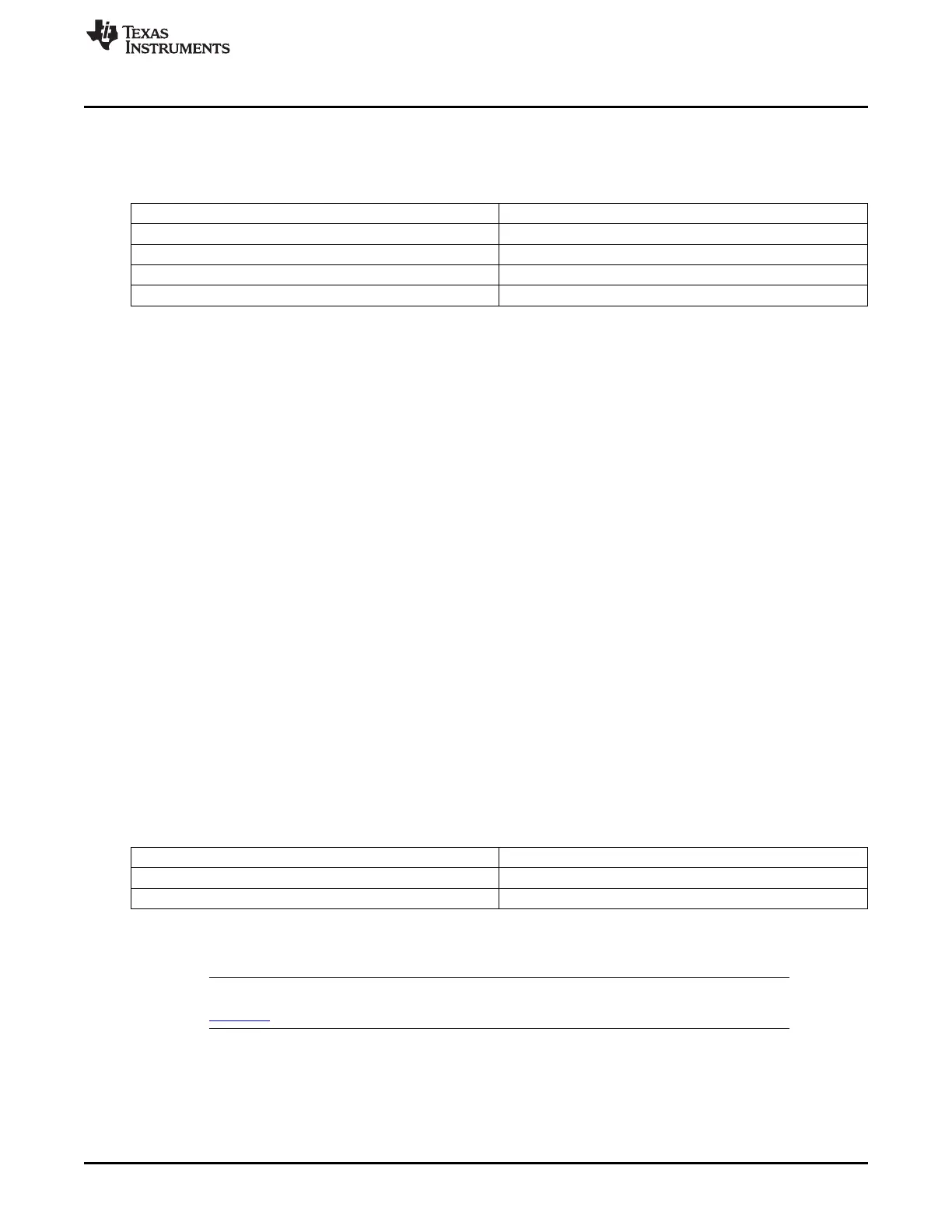
Table 26-35. Ethernet PHY Mode Selection
SYSBOOT[7:6] PHY Mode
00b MII
01b RMII
10b Reserved
11b RGMII without internal delay
26.1.8.5 UART Boot Procedure
26.1.8.5.1 Device Initialization
• UART boot uses UART0.
• UART0 is configured to run at 115200 baud, 8-bits, no parity, 1 stop bit and no flow control.
26.1.8.5.2 Boot Image Download
• UART boot uses x-modem client protocol to receive the boot image.
• Utilities like hyperterm, teraterm, minicom can be used on the PC side to download the boot image to
the board
• With x-modem packet size of 1K throughout is roughly about 4KBytes/Sec.
• The ROM code will ping the host 10 times in 3s to start x-modem transfer. If host does not respond,
UART boot will timeout.
• Once the transfer has started, if the host does not send any packet for 3s, UART boot will time out
• If the delay between two consecutive bytes of the same packet is more than 2ms, the host is
requested to re-transmit the entire packet again
• Error checking using the CRC-16 support in x-modem. If an error is detected, the host is requested to
re-transmit the packet again.
26.1.8.5.3 Pins Used
The list of device pins that are configured by the ROM in the case of UART boot mode are as follows.
Note: All the pins might not be driven at boot time.
Table 26-36. Pins Used for UART Boot
Signal name Pin Used in Device
rx uart0_rxd
tx uart0_txd
26.1.8.6 USB Boot Procedure
NOTE: See AM335x ARM Cortex-A8 Microprocessors (MPUs) Silicon Errata (literature number
SPRZ360) for limitations of USB booting.
26.1.8.6.1 Device Initialization
The ROM code supports booting from the USB interface under the following conditions:
• When the high-speed USB OTG (USBOTGHS) IP is used through USB0 interface.
• USB operates in full-speed, client mode.
4147
SPRUH73H–October 2011–Revised April 2013 Initialization
Submit Documentation Feedback
Copyright © 2011–2013, Texas Instruments Incorporated

 Loading...


